Hi Anthony, i installed the modules today but one of the chanel has an DC off set of 0.435 V and the other chanel is 13mV. I am using the PSU three and two 35VAC transformers. Please help me to trouble shoot the problem.
Many thanks
Quan
Many thanks
Quan
Attachments
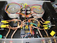
I test the module off chassis showed Dc offset only 10mV!!!. I wonder whether the issue is grounding rather than the module at all. Should the heatsink be grounded?.
Quan
Hi Quan
If it measures OK off the heat sink, check the that the VBe device between the
output devices has been insulated from the heat sink.
Cheers
Anthony
Sorry Anthony , the module was tested mounted on the heat sink but not within the chassis then the DC offset was fine ie 10mV. But once fully installed in chassis with speaker protection unit LSP then the DC offset measured 0.435V.
Quan
Quan have you earthed the main power supply to mains chassis earth?
Anthony
I have tried to re secure the earth arrangement but still not making any difference to the DC offset of the right chanel -showing 0.45V still compare to 13 mV of the left chanel. Not sure what else to do now?. Any ideas guys? Even without source or preamp connected when the power amp turn on the speaker cone went crazy.
Quan
Quan
Last edited:
Hi quan
I don't know if these are the modules you got from me, but if they are, I had DC offsets of +26mV and +4mV with my power supply.
You could try swapping the heatsink amp modules to opposite sides to see if the offset follows the amp or stays on the same side, i.e. with the power supply. Try using the power supply with 1 channel at a time with 1 transformer but I don't know the PSU three supply so might not be possible.
If there is no offset problem out of the chassis, then you may want to go back to basics.
1. With the modules out from the chassis make sure the insulators are under all the 3 devices. Check with DMM from module ground to heatsink and you should get no reading.
2. With the modules back in the case, check with DMM from heatsink to chassis ground to ensure continuity. I've had several amps where I had to run a ground wire from the heatsink to the chassis ground as paint or anodised surfaces would not allow continuity. Chassis ground then went to the main earth. The power supply ground went back to chassis ground via a 10R resistor and 2 reversed diodes.
3. Build a fast and easy power supply using 1 transformer, a bridge rectifier and 2 caps for testing purposes. ESP has some schematics for a quick power supply and wiring.
Some builders short the signal input pins when checking DC offset but I usually don't. The only time I have was with a LM4780 ChipAmp.
Cheers rabbitz
Many thanks Peter for the suggestions. I will try them out. The modules are good off the chasssis. I did measured the modules and heatsink to ensure no short. There are insulators under all trannies. I was thinking of swapping out the PSU and try another simple PSU to see if the problems persist or not. Had such a busy week end and i will endeavor to try all the suggestions.Hi quan
I don't know if these are the modules you got from me, but if they are, I had DC offsets of +26mV and +4mV with my power supply.
You could try swapping the heatsink amp modules to opposite sides to see if the offset follows the amp or stays on the same side, i.e. with the power supply. Try using the power supply with 1 channel at a time with 1 transformer but I don't know the PSU three supply so might not be possible.
If there is no offset problem out of the chassis, then you may want to go back to basics.
1. With the modules out from the chassis make sure the insulators are under all the 3 devices. Check with DMM from module ground to heatsink and you should get no reading.
2. With the modules back in the case, check with DMM from heatsink to chassis ground to ensure continuity. I've had several amps where I had to run a ground wire from the heatsink to the chassis ground as paint or anodised surfaces would not allow continuity. Chassis ground then went to the main earth. The power supply ground went back to chassis ground via a 10R resistor and 2 reversed diodes.
3. Build a fast and easy power supply using 1 transformer, a bridge rectifier and 2 caps for testing purposes. ESP has some schematics for a quick power supply and wiring.
Some builders short the signal input pins when checking DC offset but I usually don't. The only time I have was with a LM4780 ChipAmp.
Cheers rabbitz
Quan
Last edited:
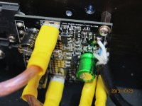
Have try a simple power supply and the Dc offset got stuck at 0.45V still. I think Anthony is right may be there is fracture smd transistor .
Quan
I think Anthony was saying fracture in the soldering joint not in the transistor itself. Reflowing the solder on the transistors that Anthony pointed out would do the trick if that's the case.
Chris
or since its multi layer board, could it have hidden cracks inside ?
btw
your amp boards only have DC problem when mounted in a box
is it the box, or just when connecting the two channels together ?
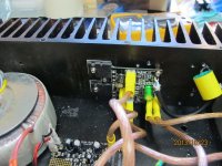
anyway, all those spade connectors and heavy wires can be quite a load for the tiny solder pads
btw
your amp boards only have DC problem when mounted in a box
is it the box, or just when connecting the two channels together ?
anyway, all those spade connectors and heavy wires can be quite a load for the tiny solder pads
Hi Quan,
Was just checking we were all on the same page. Hope Anthony's able to sort it out for you") I'm still enjoying my nxv203 amps here!
I'm still enjoying my nxv203 amps here!
tinitus,
I could be wrong but I'm pretty sure this is a 2layer board, unlikely to have a cracked via.
You've made a good suggestion about connecting the two so that they share a ground but without the chassis.
Chris
Was just checking we were all on the same page. Hope Anthony's able to sort it out for you
I'm still enjoying my nxv203 amps here!tinitus,
I could be wrong but I'm pretty sure this is a 2layer board, unlikely to have a cracked via.
You've made a good suggestion about connecting the two so that they share a ground but without the chassis.
Chris
- Status
- This old topic is closed. If you want to reopen this topic, contact a moderator using the "Report Post" button.
- Home
- Holton Precision Audio
- HPA-nvX200 signature modules