I never connected more than 2 chips to one transformer. There are some tradeoffs and gains when increasing wattage (although I can't really define them clearly as I didn't experiment enough). From what I remember, with smaller transformers you get more speed and immediacy, with bigger, you gain body and deeper bass, although it may seem a bit "heavy" without enough articulation.
However, since you are aiming at 3 LM4780 chips, which are more current hungry, it may work fine for you.
However, since you are aiming at 3 LM4780 chips, which are more current hungry, it may work fine for you.
Hi folks
I got my premium DAC kit from Peter( who was very prompt in attending to my order, Thanks Peter!) a few days ago and am just starting on it. I had my eye on a DAC for along time, and this looks like the real McCoy My players have an optical output so I am getting a Torx179 receiver to replace the one that Peter sent-I didnt look at the outputs before ordering.
I have ordered a 30VA toroidal locally, and am loking at various possible enclosures. Any suggestions welcome.
George
Bangalore, India
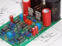
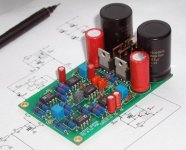
I'm getting ready with finalizing the buffer stage. The board is ready for testing. Adding the quality attenuator at the input may create quite a good preamp (at least that's what I'm hoping for).
Each board is one channel; complete PS is on board (only transformer needs to be connected). For balance configuration, when two boards are needed per channel, they can be stacked, sharing same supply.
I worked on that board design with Veteran, a diy forum member. This is the same person that was behind the Green DAC board design")
Schematic attached (please note that regulators need to be swapped, they are marked incorrectly).
Each board is one channel; complete PS is on board (only transformer needs to be connected). For balance configuration, when two boards are needed per channel, they can be stacked, sharing same supply.
I worked on that board design with Veteran, a diy forum member. This is the same person that was behind the Green DAC board design
An externally hosted image should be here but it was not working when we last tested it.
Schematic attached (please note that regulators need to be swapped, they are marked incorrectly).
Attachments
Peter Daniel said:I'm getting ready with finalizing the buffer stage. The board is ready for testing. Adding the quality attenuator at the input may create quite a good preamp (at least that's what I'm hoping for).
Excellent timing Peter. But, I don't see any tubes.
 I'd almost think you're purposely trying to get me to give up tubes altogether, other than the fact you don't know me.
 Regards,
Wade
Peter Daniel said:The DAC wasn't really designed to work with computer soundcards, although some people use it like that.
Without input driver present and correct connection to CS8412 the output is inverted. I'm not sure if you can correct it by swapping connection to the receiver, but you may try (it will probably depend on source output)
For reference, this is possible, at least in my config.
It sounds quite different with the phase non inverted, I can't connect my 'phones backwards so this was quite important for me.
Approaching 40 hours now and it is really sounding good, happy at last, very happy!

Output Buffer
Peter,
What is the approximate gain of the buffer stage, and what is the impedance matching range for input source and output .....what are the potential applications you envision (in addition to pre-amp)?
How far off is the board availability, and are you thinking of kits, or just boards?
Robert
Peter Daniel said:I'm getting ready with finalizing the buffer stage. The board is ready for testing. Adding the quality attenuator at the input may create quite a good preamp (at least that's what I'm hoping for).
Each board is one channel; complete PS is on board (only transformer needs to be connected).
Peter,
What is the approximate gain of the buffer stage, and what is the impedance matching range for input source and output .....what are the potential applications you envision (in addition to pre-amp)?
How far off is the board availability, and are you thinking of kits, or just boards?
Robert
Re: Output Buffer
It should work fine
The buffer has unity gain. It may work very well with good quality attenuator at the input (like Placette for instance) improving passive volume control performance.
It may also work well at the output of the DAC or CD player, when low impedance is required (the buffer output imp is 6 ohm). It is then more appropriate to use TVC, especially when 4.7 BG N caps in a DAC can be now replaced with quality teflons at much lower value (0.1uF for instance) and much lower price (still $40 for V-Caps).
Since the components are not easy to obtain (minimum order is 50 pcs from D-K or AD) I will be probably offering complete kits. The boards are already fabricated and I have them available.
Destroyer OS. said:500VAC to big at 24v? I have one of those I think.
It should work fine
rjkdivin said:
What is the approximate gain of the buffer stage, and what is the impedance matching range for input source and output .....what are the potential applications you envision (in addition to pre-amp)?
How far off is the board availability, and are you thinking of kits, or just boards?
The buffer has unity gain. It may work very well with good quality attenuator at the input (like Placette for instance) improving passive volume control performance.
It may also work well at the output of the DAC or CD player, when low impedance is required (the buffer output imp is 6 ohm). It is then more appropriate to use TVC, especially when 4.7 BG N caps in a DAC can be now replaced with quality teflons at much lower value (0.1uF for instance) and much lower price (still $40 for V-Caps).
Since the components are not easy to obtain (minimum order is 50 pcs from D-K or AD) I will be probably offering complete kits. The boards are already fabricated and I have them available.
I'm not sure if this would be an upgrade, any active circuit will bring certain coloration and loss of resolution.
However, the DAC circuit has rather high output impedance (approx 3k) so it may not be reaching full potential with some line stages (that have lower input imp). For instance, I prefer using the DAC with active preamp (100k impedance) and not that much with TVC. But using a buffer with low output impedance may change things somewhat
Besides, the buffer is needed for the preamp stage I'm trying to finalize soon.
Better thus to add this buffer as a front section of that preamp (isn't that also what ML uses?). I use my DAC with a BoZ at the moment. Pretty pleased with that. I upgraded it and prefer it now above the bosoz that I used unbalanced.
This project however would be a good use for my stock of 2210's and 2220's I have laying around.
Your PCB layout skills greatly surpass any I have seen, So PCBs would be very welcome
This project however would be a good use for my stock of 2210's and 2220's I have laying around.
Your PCB layout skills greatly surpass any I have seen, So PCBs would be very welcome
The input circuit inside ML380 looks like that:
Following, is a volume control based on a DAC and AD825 used for I/V. The buffer completes the output.
Unmodified, the preamp sounds average, even the S version. After modifications (changed chips, diodes, caps and some resistors) the circuit sounds pretty decent and that's what I currently use it in my secondary system.
However, there is a still room for an improvement, and that's what current project is aiming at.
BTW, the same type buffer is also used in this DAC:
An externally hosted image should be here but it was not working when we last tested it.
Output Buffer
Peter,
When you get the pricing for the boards and or kits worked up, will you be listing them at AudioSector, or on the forum?
Robert
Peter Daniel said:
Since the components are not easy to obtain (minimum order is 50 pcs from D-K or AD) I will be probably offering complete kits. The boards are already fabricated and I have them available.
Peter,
When you get the pricing for the boards and or kits worked up, will you be listing them at AudioSector, or on the forum?
Robert
- Status
- This old topic is closed. If you want to reopen this topic, contact a moderator using the "Report Post" button.
- Home
- More Vendors...
- Audio Sector
- AudioSector-chip amp kits, dacs, chassis