>> I'm just telling you what sounds best ")
That's what I love to hear. Thanks.
>>Transormers have voltage regulation margin, which allows specified
>> voltage at full current draw. With normal amp use (or bigger than
>>neccessary transformer) it will never happen, that's why higher
>>voltage than you calculate using formulas.
I see. That makes sense. I didn't know about that.
..Todd
Peter Daniel said:I'm close to finilizing an output buffer stage that can be used in a preamp or DAC. Here's the proposed board layout. The board contains one audio channel and a complete PS (except for transformer). The size is about 2 x 4" .
Peter,
How is your output buffer project coming along? Or have you been too busy to work on it?
Robert
Peter Daniel said:The PCB is being finilized as I write it. If things go well, it might go into production next week. As the first batch will be fabricated in Europe, it will take some additional time before I get it here, but it shouldn't be more than a month or so.
Peter,
I'm sure you will keep us up to date......I am interested in building it when ready.
My 2 DACs and LM3875 kit arrived yesterday.....thank you. The boards look great and I am starting to populate them.
For the LM3875s, you mentioned an alum plate heatsink about 3x3x0.5 (in free air). Your example shows using the aluminum chassis walls. If you wanted to use fin type heatsinks inside a chassis, do you have a degC/W rating recommendation?....or an approx. size?
Robert
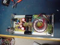
if anyone wanted to use a donut instead of the other transformer
this place has a box full at $2.00 each new
its not on the webpage but there in the store.
8.5volt
http://www.fcsurplus.com/index_2.htm
this place has a box full at $2.00 each new
its not on the webpage but there in the store.
8.5volt
http://www.fcsurplus.com/index_2.htm
Attachments
4780 board
Hi Peter,
I received the 4780 board and components today. The board looks amazing. Even my wife was impressed. Kudos.
Question: I've just been reading through this thread from the beginning, but I cannot find any reference to the four 10uF/50v caps that were packaged with the diodes. They're not listed on the schematic on your site, which doesn't really cover the rectifier board.
I'm a little confused about how the board(s) should be populated for the parallel configuration. Particularly regarding those caps. Can you point me towards the necessary information?
Thanks.
..Todd
Caveat: If this is wrong or inappropriate, I'm sure someone will correct me.
Peter's boards are similar to BrianGT's (they developed the original versions together, I think. I believe the 10uF Panasonic are used in the same position that the 4.7uF Black Gate N's are used on the rectifier board. Check the brianGT assembly guide here for more info.
Hope this helps! Peter and Brian have both created works of art. I think one of my projects will be to build one Peter's gold plated LM3875 amps so it hangs on the wall
If you go to my site and enter the LM4780 page: http://www.audiosector.com/lm4780.shtml you will see a link to "Applications Notes": http://www.diyaudio.com/forums/showthread.php?postid=636556#post636556 This is where I explained different configurations possible with that board. The board is the step up from the previous design, and offers more options, including bridged/parallel/stereo configurations and snubbers (idea originated by CarlosFm).
Regarding 10u caps, it is recommended to try them in a circuit and decide if they bring improvement or not. Recently, when going with 1500u caps, I'm using 10u cap on negative rail only
http://www.diyaudio.com/forums/showthread.php?postid=584436#post584436
Regarding 10u caps, it is recommended to try them in a circuit and decide if they bring improvement or not. Recently, when going with 1500u caps, I'm using 10u cap on negative rail only
http://www.diyaudio.com/forums/showthread.php?postid=584436#post584436
Hi Peter,
I have a spare Plitron 2114 power torroid from a Zen project abandoned when it was decided not to build something drawing enough current to soften power cords. It's 2x25 VAC at 1000 VA. I'm looking for an alternate reference for voicing SET amps, is this transformer a suitable match for one of your kits?
I have a spare Plitron 2114 power torroid from a Zen project abandoned when it was decided not to build something drawing enough current to soften power cords. It's 2x25 VAC at 1000 VA. I'm looking for an alternate reference for voicing SET amps, is this transformer a suitable match for one of your kits?
I'm running the LM4780s on 42V rails at the moment, as I stole the 27-0-27 traffo I was using to test another project. They still work, but do get very warm. If you want to repeat this, you will need BIG heatsinks, or fan cooling, and I'm not going to give any guarantees as to long term reliability. It doesn't help the sound either, higher rails seem to close in the dynamics a little.
Peter Daniel said:If you go to my site and enter the LM4780 page: http://www.audiosector.com/lm4780.shtml you will see a link to "Applications Notes": http://www.diyaudio.com/forums/showthread.php?postid=636556#post636556 This is where I explained different configurations possible with that board. The board is the step up from the previous design, and offers more options, including bridged/parallel/stereo configurations and snubbers (idea originated by CarlosFm).
I know, I've read it all a few times through. Lots of very helpful photos, but I'm not sure I'd agreed it was explained very well. The schematic on your site covers the amp circuit nicely, but there isn't a schematic or parts list for the power supply board. C1, C2, C3, C4? ... they aren't listed or explained. When you talk about snubbers and bypass caps, it's not obvious to me which you are referring to.
Regarding 10u caps, it is recommended to try them in a circuit and decide if they bring improvement or not. Recently, when going with 1500u caps, I'm using 10u cap on negative rail only
http://www.diyaudio.com/forums/showthread.php?postid=584436#post584436
So, would the 10u cap placement be labelled as C2 on the rectifier board?
Thanks,
..Todd
motherone said:Peter's boards are similar to BrianGT's (they developed the original versions together, I think. I believe the 10uF Panasonic are used in the same position that the 4.7uF Black Gate N's are used on the rectifier board. Check the brianGT assembly guide here for more info.
Motherone: I missed your message first time through. Good info. Thanks! That clears up a lot of confusion.
..TAJ
Thanks all. The somewhat high voltage was my concern, from memory the datasheets appear to indicate something in the 18 VAC range as the best compromise between power output and avoiding being 'Spiked' by lowish loads. I don't need much power, just a good match. Thanks again.
Re: 4780 board
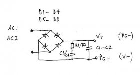
Here's the simplified schematic of rectifier's board. C1/C2 are optional and I suggest experimenting with using them (they may improve sound or they might degrade it, depending on your taste and system). Supplied value is 10uF.
For any configuration of amp board, placement of those caps (10u) is not critical and amp will work equally well with those caps or without them. By installing them, you can manipulate amp's sonic signature, and here choice should be yours.
The different configurations of amp board were extensively described in the links I posted previously, but if you have any additional questions, don't hesitate to ask.
With regards to snubber components, those parts are not supplied with a kit, and are optional. The best is to ask CarlosFm for current values, as he changes them quite frequently. At the time the board was developed R1/R2 was 1R and C3/C4 0.1uF. The other resistor (if you find his schematic) has to be soldered directly to cap's pins.
Personally, I don't recommend using the snubber.
taj said:Question: I've just been reading through this thread from the beginning, but I cannot find any reference to the four 10uF/50v caps that were packaged with the diodes. They're not listed on the schematic on your site, which doesn't really cover the rectifier board.
I'm a little confused about how the board(s) should be populated for the parallel configuration. Particularly regarding those caps. Can you point me towards the necessary information?
Here's the simplified schematic of rectifier's board. C1/C2 are optional and I suggest experimenting with using them (they may improve sound or they might degrade it, depending on your taste and system). Supplied value is 10uF.
For any configuration of amp board, placement of those caps (10u) is not critical and amp will work equally well with those caps or without them. By installing them, you can manipulate amp's sonic signature, and here choice should be yours.
The different configurations of amp board were extensively described in the links I posted previously, but if you have any additional questions, don't hesitate to ask.
With regards to snubber components, those parts are not supplied with a kit, and are optional. The best is to ask CarlosFm for current values, as he changes them quite frequently. At the time the board was developed R1/R2 was 1R and C3/C4 0.1uF. The other resistor (if you find his schematic) has to be soldered directly to cap's pins.
Personally, I don't recommend using the snubber.
Attachments
rdf said:Thanks all. The somewhat high voltage was my concern, from memory the datasheets appear to indicate something in the 18 VAC range as the best compromise between power output and avoiding being 'Spiked' by lowish loads. I don't need much power, just a good match. Thanks again.
Actually, non inverting configuration seem to sound better with higher voltage. I'm using at least 34V DC per rail, but I'm cdeliberating now switching to even higher voltage.
I was doing some tests with amp connected through the variac, and by increasing the voltage sound was improving as well. Running the amp from 24V batteries produces rather sleepy sonic signature
Yes, LM3875.
So far people commented that LM3875 has better top end and midrange, when comparing to LM3886 (or LM4780). The other two chips show more "body" and might provide better drive, but for sheer transparency and delicacy of the sound, LM3875 would be still a preferred choice. However, in some systems it may sound a bit thin or even analytical. It's best to build the system around such amp and not trying to fit the amp into existing system
So far people commented that LM3875 has better top end and midrange, when comparing to LM3886 (or LM4780). The other two chips show more "body" and might provide better drive, but for sheer transparency and delicacy of the sound, LM3875 would be still a preferred choice. However, in some systems it may sound a bit thin or even analytical. It's best to build the system around such amp and not trying to fit the amp into existing system
- Status
- This old topic is closed. If you want to reopen this topic, contact a moderator using the "Report Post" button.
- Home
- More Vendors...
- Audio Sector
- AudioSector-chip amp kits, dacs, chassis