funberry said:Please educate me on something:
How does this "snubberrized" rectifier approach translate into a better power supply?
All in all, I have not been able to find any difference in sound quality measured at the Amplifier output with a "snubberized" Power Supply, versus a plain vanilla bridge.
If you have found different, what test setup did you use?
I never measure sound quality, I only listen.
My listening observation indicated that snubberised supply is not better than a regular one, just different.
funberry said:Please educate me on something:
How does this "snubberrized" rectifier approach translate into a better power supply?
True, convectional silicon rectifiers, have some switching delays that may be addressed by the "MUR" part types, but these times are measured in nanoseconds! And this is 60Hz!
And conduction losses between a .6V drop and a .3V drop are not relevant in a highly filtered, unregulated PS like this one.
And "snubber" really deals with providing a conduction path for backEMF or energy stored in an inductor, neither of which are present here (I've checked this with an oscilloscope).
Although it's easy to demonstrate that bridge rectifier switching sends sufficient current harmonics back into the power line to pollute the mains, this is not an issue with North American compliance, as it it with CE (a bridge rectifier won't pass CE without some form of power factor correction).
All in all, I have not been able to find any difference in sound quality measured at the Amplifier output with a "snubberized" Power Supply, versus a plain vanilla bridge.
If you have found different, what test setup did you use?
you have misdunderstood this forum's definition of "snubber". you are thinking of a cap across each diode. this is not what carlos' snubber is about. carlos' snubber is an RC in parallel with the hot and ground. check out his schematic here:
http://www.diyaudio.com/forums/showthread.php?postid=704775#post704775
Nice to hear from somebody from Montreal, my old home town.
I'm aware of the RC network. The 1.5nF cap actually does a better job alone accross the rails than with the resistor (scope traces show better transient response).
The R only adds some parasitic inductance (especially since at that power and value, it's likely to be wirewound)
And I was questioning the role of MUR860 superfast rectifiers. As an engineer with Motorola (now ONsemi), having worked with Schottky and fast recovery rectifiers for 23 years, I can say there is no engineering advantage to them at 60Hz. And they may in fact cause more transients because they switch very hard, compared to conventional rectifiers.
My apologies, though.
I now realize some things should not be questioned.
Just believe; do not question.
Could it be that you are asking the wrong questions? In the wrong place?Just believe; do not question.
Are you saying the type of rectifier has no influence on sound quality? Because it looks like that is what you are saying. But I don't want to put words into your mouth.having worked with Schottky and fast recovery rectifiers for 23 years, I can say there is no engineering advantage to them at 60Hz.
This I won't question. And I believe you.And they may in fact cause more transients because they switch very hard, compared to conventional rectifiers
It's not really a question of belief
It's just a question of whether you have tried it and LISTENED to the results.
For the people that HAVE tried various options, heard a difference and draw conclusions as a result, other peoples theories, that are not based on personal listening experience, don't really hold much truck I guess.
So I honestly do not think anyone here is wanting you to believe in their ideas / techniques. But, rather that critisise others ideas, why not just dip your toe in the water and find out what you own preferences are.
You may be suprised how small changes do effect the sound and you also might have to admit to yourself that you don't fully understand why.....")
join the club...
good luck
mike
It's just a question of whether you have tried it and LISTENED to the results.
For the people that HAVE tried various options, heard a difference and draw conclusions as a result, other peoples theories, that are not based on personal listening experience, don't really hold much truck I guess.
So I honestly do not think anyone here is wanting you to believe in their ideas / techniques. But, rather that critisise others ideas, why not just dip your toe in the water and find out what you own preferences are.
You may be suprised how small changes do effect the sound and you also might have to admit to yourself that you don't fully understand why.....
join the club...
good luck
mike
I am convinced that I'm asking the wrong questions, in the wrong place.
Looking at some of these designs, it appears that there has been an honest effort to improve, whatever could be improved, here and there.
Someone has gone through the parts list saying " I want the best RCA jacks, the best binding posts, the best wire, the best capacitors, etc. How can I improve the diodes, how can I do better here, or there...
This sweeping improvement effort is commendable, although in some areas it may be a bit suboptimal.
If you have 10,000uF filter capacitors on the supply rail, does it really matter what happens at the rectifier diodes? In my opinion, a sorage inductor in series with the supply line, just before the filter capacitor could be a greater benefit in improving quality than fast-recovery rectifiers. This way you would have a two-pole filter, and the power supply ripple should be reduced to half.
Another thing I will try is reducing the ESR and series inductance of the El caps.
This would mean using several lower value capacitors in parallel instead of a single larger one. It is known that higher voltage/lower value El-caps tend to have lower parasitic inductance and resistance. The parallelling will also reduce parasitics. Also, for best transient response, I would parallel as many different types and values of capacitors as is practical.
For example, 3x 10,000 uF, 2x100uF, 2x 1uF, 2x .1uF, 2x.001uF, diversifying accross different technologies (some mylar, some ceramic monolythics, some electros).
Furthermore the Electrolytic caps are the most prone to failure and aging, since they contain a liquid, which can evaporate. There are more failures on electronic circuit boards today from electrolytic capacitors, than from any other component type, and often semiconductor failures can be traced to a pre-occuring capacitor failure.
Not long ago, Nichicon had shipped out batches of electrolytics made with an inferior grade of chemical from an unknown Chinese company. Many of these capacitors failed, and caused great losses to industrial customers. A couple of switching power supply mfrs located in Asia actually filed lawsuits against Nichicon for this.
All in all, this tells me if I use electrolytics in a critical function, I should distribute the risk among 2, 3, 4, caps instead of one, preferably of different makes. I know, this sounds like a nightmare for someone who has to design PCBs, but I'm just telling it like it is. What's more, distributing capacitor risk by parallelling is doable, and inexpensive as a quality improvement initiative.
Cheers
Adrian
Hallo Adrian,I am convinced that I'm asking the wrong questions, in the wrong place.
I asked this because it is a Vendor's thread meant to ask questions about the products and not for long discussions about the merits or lack thereof of snubbers.... there are plenty of big threads on snubbers. Peter will probably ask us to move all of this to a different venue.
But I am always drawn to real engineers's remarks....and have respect for their education...because I am trying to learn. However diy'ers do things engineers sneer or laugh at.. Like the gainclone using 1500uF's...or using tube rectification..etc. But instead of trying to explain to us why that is nonsense...they might as well try to find out why there might be merit to it rather than dismiss what we are hearing (or believe what we are hearing if you will) and in the process telling us we are mad. Conversely diy'ers should always try to listen to the reality checks of engineers... tit for tat..cable do make a difference IMO..but some of the things we hear simply can't be measured or the wrong thing is being measured.
Best regards,
Bas
An interesting thread discussing high speed rectifiers can be found here: http://www.diyaudio.com/forums/showthread.php?s=&threadid=12539&highlight=
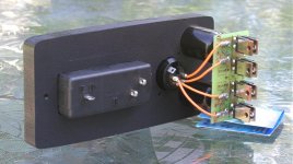
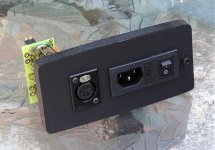
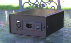
When I was coming up with a new PS board, I didn't really suspect how many possible implementations would be available. Here's one such example. This is a back panel of Patek standard PS. It's made out of 1/2 thick polypropylene board (used on boats for flooring); the material is very easy to machine and still flexible enough, so tight fit in metal tubing is easily achievable.
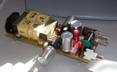
There are holes made to insert BG 1000u caps, those caps support rectifiers board with output connected to Neutric female socket. Four AC wires connect from transformer.
There are holes made to insert BG 1000u caps, those caps support rectifiers board with output connected to Neutric female socket. Four AC wires connect from transformer.
Attachments
I've finally managed to clean up all the mods on the NOS DAC. Here's the pic of a final version. The output caps are teflon V-caps (in my case 0.1uF is enough with 100k input on the preamp), I/V resistors are Caddock TF020, main filter caps are BG N 1000/50.
As presented, all components fit the board (in some way). I tried copper foil over the caps, but didn't like the result. Also, it seems like rubber band across two caps improves things somewhat.
I also removed input coupling caps, as with ML31.5 transport I'm using presently, they are not needed, and I gain a bit more of resolution.
Regarding fuse, I still keep it, as the DAC is in a stage of development, but I removed the wire from fuse housing and soldered it directly to the pads. For obvious reasons, I will not show how it looks in a picture
I can put this (modified) DAC against ML360S, and I have to think really hard, why I would still like to keep the Levinson DAC.
Attachments
- Status
- This old topic is closed. If you want to reopen this topic, contact a moderator using the "Report Post" button.
- Home
- More Vendors...
- Audio Sector
- AudioSector-chip amp kits, dacs, chassis