NOS DAC accepts I2S input?
Hi Peter
I've been reading about Ian's I2SFIFO re-clocker project:
http://www.diyaudio.com/forums/digi...ifo-project-ultimate-weapon-fight-jitter.html
- I know your DAC accepts spdif or usb inputs but with modifications, could it also work with an I2S input from the above re-clocker (I guess directly into the 1543 DAC chip), or is this not possible?
Thanks
Yes, that would be correct connection.
thank you, Peter.
Hi Peter,
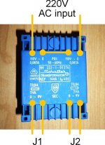
i'm reading 11.8V AC from this transformer's outputs. after rectification it should be around 17V DC. is it high or safe? AN800X datasheet says that max input voltage is 20V but there are 16V small BG electrolytics are on the board. what should i do?
thanks in advance..
i'm reading 11.8V AC from this transformer's outputs. after rectification it should be around 17V DC. is it high or safe? AN800X datasheet says that max input voltage is 20V but there are 16V small BG electrolytics are on the board. what should i do?
thanks in advance..
Attachments
11.8 x 1.414 = 16.68 - 2 diode drops ( 1.26 ) = 15.42V
As soon as you ask the transformer to do some work the voltage will fall again depending on how much current your circuit will draw - could easily be another 1 - 2V which would give around 13.5 - 14.5V.
Looks like u'll be safe to turn it on to measure actual voltages.
You could try putting the 20R peter suggested in both legs ( apply ground after CRC )
If it were me I'd aim for around 12V before regulators
mikelm, thank you.. there are four 20R resistors under the board, do i need additional 20R resistors?
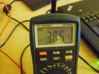
AndrewT, i did your advices with and without smoothing cap and i got this absurd results: 3.65V
also i tried different type of rectifier (kbpc3510) on one output (i have only one on hand) with same result. i'm still reading 11.6V on the output of the transformer and 220V on the input, so my dmm can't be wrong..
what's wrong i'm doing? thanks..
Attachments
mikelm, thank you.. there are four 20R resistors under the board, do i need additional 20R resistors?
Can't really comment on that without circuit diagram - it depends how those 20Rs are connected
Add a small bridge rectifier and small smoothing capacitor to your transformer secondary.
Measure the "no load" output voltage of the PSU..........
without a smoothing capacitor !!!!!...............AndrewT, i did your advices with and without smoothing cap and i got this absurd results: 3.65V
also i tried different type of rectifier (kbpc3510) on one output (i have only one on hand) with same result. i'm still reading 11.6V on the output of the transformer and 220V on the input, so my dmm can't be wrong..
what's wrong i'm doing? thanks..
Why?
Do what you have been told, or simply ignore and go away.
Your choice.
If you don't have a cap after the diodes the whole dynamic of the supply is changed.
If you want to go that route you have to design it that way from scratch but it is radically different and not really necessary for such a low power circuit.
if you don't really understand this stuff best follow the kit as described by Peter before somethings goes horribly wrong !
Good Luck !
mike
If you want to go that route you have to design it that way from scratch but it is radically different and not really necessary for such a low power circuit.
if you don't really understand this stuff best follow the kit as described by Peter before somethings goes horribly wrong !
Good Luck !
mike
AndrewT, i didn't want to be annoying you, just was experimenting to write results here.. i learnt lots of things from you here and i always thankful to you..
i find what i'm doing wrong; simly forgotting to switch my dmm after reading transformer's output voltage, ac to dc..
so i wired again with capacitors") and read that 14.64V and 14.88V. it should be around 13.4-13.6 after 20R resistors and around 12-12.5 under load.. it looks like safe..
and read that 14.64V and 14.88V. it should be around 13.4-13.6 after 20R resistors and around 12-12.5 under load.. it looks like safe..
thanks for your helps..
i find what i'm doing wrong; simly forgotting to switch my dmm after reading transformer's output voltage, ac to dc..
so i wired again with capacitors
and read that 14.64V and 14.88V. it should be around 13.4-13.6 after 20R resistors and around 12-12.5 under load.. it looks like safe..thanks for your helps..
- Status
- This old topic is closed. If you want to reopen this topic, contact a moderator using the "Report Post" button.
- Home
- More Vendors...
- Audio Sector
- AudioSector-chip amp kits, dacs, chassis