Re: 2nd One
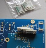
Actually R8 and R9 are first to be replaced. Those are I/V resistors and if you check the traces underneath, they both connect with output coupling caps. In some setups using Caddocks here, in place of Rikens, may be beneficial (but may still require choosing different output caps).
Recently it's been brought to my attention that placing Caddock TF020 for R7 also improves things a bit, so you may try it as well (1k5)
All 3 Caddocks will fit in top layer, R7 needs pin properly formed.
rjkdivin said:R7 and R9 are the correct ones to replace....correct Peter? I noticed you added the Caddock-spaced thru hole pads at R8 and R9, but not R7, and it threw me off a little.
Actually R8 and R9 are first to be replaced. Those are I/V resistors and if you check the traces underneath, they both connect with output coupling caps. In some setups using Caddocks here, in place of Rikens, may be beneficial (but may still require choosing different output caps).
Recently it's been brought to my attention that placing Caddock TF020 for R7 also improves things a bit, so you may try it as well (1k5)
All 3 Caddocks will fit in top layer, R7 needs pin properly formed.
Attachments
Re: 2nd One
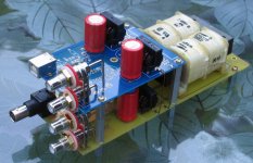
I made a similar setup, in case both SPDIF and USB DACs are needed (and fed from common supply). I didn't want to go into switching I2S lines, not to compromise the performance.
The rectifiers and C1/C3 are common to both DACs, everything else is separate. The supply connections are done through pair of wires on each side, from the pads sideways to rectifiers (now you know what they were intended for")
You may install 2PDT switches on each side to disconnect power from DAC on top.
rjkdivin said:I'm planning to build two more boards without the PSU section, or at least without the inlet and transformer, and put them into the cases I built for my two NOS DACs, sharing one PSU switched between the two DACs in each case.
It looks like the PCB cut could be made to feed the second board from the first transformer secondary (so the PSU diodes, caps and inductors would be duplicated); or you could cut it right behind the inductors and make the connection at R1,2,3,4 (so none of the PSU would be duplicated). To switch the PSU between the two boards would require a 4PDT switch? Any suggestions?
I made a similar setup, in case both SPDIF and USB DACs are needed (and fed from common supply). I didn't want to go into switching I2S lines, not to compromise the performance.
The rectifiers and C1/C3 are common to both DACs, everything else is separate. The supply connections are done through pair of wires on each side, from the pads sideways to rectifiers (now you know what they were intended for
You may install 2PDT switches on each side to disconnect power from DAC on top.
Attachments


Peter,
Very interesting in LM3875 but have some question before I mail you for order (DAC & amp).
My speaker is only 6ohm, 88Hz Sonus faber bookshelf
My taste of music: Jazz, pop. I'm not are rock fan,
Does LM3875 suitable for my speaker, do you suggest me to brigd/paranel or looking else ?
For DAC i'll contact you via email, for Amp i can order via audio sector, is it?
Many thanks for your advise
All,
Some concern on transformer need help.
For LM3875, should we use 2 transformer 160 VA mono block or 1 of 300 VA or 2 300 VA transformers, what option extract best performance from LM3875. For 6 ohm speaker, what Dc voltage workbest: 18, 20, 22, or 25 V DC. Becasuse i can customer make for trans. We use 220V AC in our country.
Many thanks
the chip can do upto 60W into your chosen load.bfslm said:For LM3875, should we use 2 transformer 160 VA mono block or 1 of 300 VA or 2 300 VA transformers, what option extract best performance from LM3875. For 6 ohm speaker, what Dc voltage workbest: 18, 20, 22, or 25 V DC.
Using the normal factor, this requires a transformer with a VA rating of between 60VA and 120VA.
But small transformers have a high regulation value. This results in a high quiescent voltage making the chip run hotter than necessary and also results in the supply voltage sagging badly on longer duration transisents.
I think your suggestion of 160VA is probably about right for a single channel chipamp (monoblock).
If you can get a slightly bigger transformer cheaply then there is a small benefit in reduced regulation.
If you want two channels, then the transformer should be between 120VA and 240VA. Your 160VA would do just nicely for two channel as well. Two channel is more difficult to get hum free operation.
I recommend a supply voltage between 56Vdc(+-28V) and 70Vdc(+-35V) for 6ohm speaker and preferably at the lower end, particularly since the max output current is 4A to 6A when the chip is cold.
You need to identify your transformer and find out it's regulation, then you can decide which AC voltage you require to give your target DC voltage.
Many thanks Andrew for your sugestion, I actually very newbie in this DIY section so need to learn alot from your guy who have lots of experience.
with your suggestion, I may op to go with 2 x 225 VAC transformer(mono block), 9% regulation typical, 30 VDC secondary . Is it good?. Peter recommended of using 22VDC supply voltage????
A bit concern me, You recommended of 56VDC- 70VDC supply voltage but Peter recommended that transformer for LM3875 must have supply voltage of <42VDC,
Again thank you
bfslm said:For LM3875, should we use 2 transformer 160 VA mono block or 1 of 300 VA or 2 300 VA transformers, what option extract best performance from LM3875. For 6 ohm speaker, what Dc voltage workbest: 18, 20, 22, or 25 V DC. Becasuse i can customer make for trans. We use 220V AC in our country.
While transformer ratings given above will work fine from technical POV, over the years I noticed that for some reason bigger transformer is better sonically. So presently I'm using 300VA units only (either for mono or stereo) with 2 x 22V AC secondaries. This produces approx 34V DC rail voltage.
"56VDC- 70VDC" suggested previously was voltage between rails.
300VA transformers are also recommended for dual mono configuration (although 220VA will work fine too).
As to the LM3875 chip configuration, I don't recommend paralleling. Bridging would be good, but with 6ohm load it is not really suitable (although it will work). Besides, you would need a balanced source/preamp. So a single chip per channels is the way to go.
Many thanks Peter,
Clear now for transformer selection. I'll go with 300/2x22VDC.
Few question.
- What's size of PBC board, both amp and rectifiers boards, with heigh, for premium kit and upgraded with BG BGN100/50 and BG STD 1000/50 as Peter recommended.
- Can I order BG BGN100/50 and BG STD 1000/50 from you as well and what's price of upgraded premium kit (LM3875). How can I order it via audiosector (with BG upgrade).
Still can not contact Peter via email for DAC order cause new register.
Rgds,
Both amp and rectifiers PCB size is 30x74mm. The caps height as follows:
Panasonic FC1500/50 36mm
BG N 100/50 31mm
BG STD 1500/50 41mm
You can get those caps from me. My direct email address can be found here: http://www.audiosector.com/contact.asp
Panasonic FC1500/50 36mm
BG N 100/50 31mm
BG STD 1500/50 41mm
You can get those caps from me. My direct email address can be found here: http://www.audiosector.com/contact.asp
Peter, I have a LM4780 gainclone from you in parallel configuration. How would I go about to lowering the gain on the LM4780 to match the gain of the Aleph 3. I am planning to use them for bi-amping with the Aleph3 powering the tweets and the LM4780 to power the mids of my Epos ES11 speakers.
Thanks.
Thanks.
Hello Peter,
I have a DAC with a passive output (a DDDac), and am thinking of running it through a low Zin passive pre. Not ideal, so think a buffer on the dac output may be the solution -- and your posts and schematic for the ML-based buffer caught my eye... and was wondering if PCB's are available?
rgds ssmith
Safetyman,
Peter's circuit is based on the datasheet one, albeit with carefully chosen components to maximise performance, so you can use that info to calculate the two resistors you need to change, (sorry, I can't remember offhand their designations). Just one point to be aware of, don't go below a gain of ten or the amp will become unstable.
Peter's circuit is based on the datasheet one, albeit with carefully chosen components to maximise performance, so you can use that info to calculate the two resistors you need to change, (sorry, I can't remember offhand their designations). Just one point to be aware of, don't go below a gain of ten or the amp will become unstable.
safetyman said:Peter, I have a LM4780 gainclone from you in parallel configuration. How would I go about to lowering the gain on the LM4780 to match the gain of the Aleph 3. I am planning to use them for bi-amping with the Aleph3 powering the tweets and the LM4780 to power the mids of my Epos ES11 speakers.
You can increase the value of R3/R5 to 1k5 or so. If that won't help you may also increase the input series resistors (R6/R7) to whatever value will work for you.
ssmith said:I have a DAC with a passive output (a DDDac), and am thinking of running it through a low Zin passive pre. Not ideal, so think a buffer on the dac output may be the solution -- and your posts and schematic for the ML-based buffer caught my eye... and was wondering if PCB's are available?
Yes the PCBs are available, contact me for pricing info.
http://www.diyaudio.com/forums/showthread.php?postid=805978#post805978
Peter Daniel said:
Yes the PCBs are available, contact me for pricing info.
http://www.diyaudio.com/forums/showthread.php?postid=805978#post805978
Thanks, that was the schematic I was referring to. PM sent.
- Status
- This old topic is closed. If you want to reopen this topic, contact a moderator using the "Report Post" button.
- Home
- More Vendors...
- Audio Sector
- AudioSector-chip amp kits, dacs, chassis