nycavsr2000 said:I always wondered what portion of your business was for kit builders/diyers. I'm assuming its pretty small ? Two different markets indeed.
Hi Anand,
The kits, or mostly chip amps, have been going steady for last 4 years or so. I'm still surprised that even when I'm not updating my website I get constant flow of orders. This is probably one of the best diy products ever invented
")
It's also good that I'm not only concentrating on kits but completed amps as well. When one portion of the business is slower, the other makes up for it
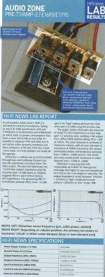
Below test report on Premium amp (kit) published recently in Hi-fi news.
Attachments
Peter Daniel said:Changing the gain by adjusting R3 may affect sonic signature of the amp. Placing 22k input series resistor (in place of R1=220R ) shouldn't probably have that much effect.
I didn't try any of those methods though, as I'm not using any active preamp and more amp gain was always desired.
I don't use an active pre either, but I have very efficient speakers and I've had trouble with too high gain earlier. I guess the best thing is to try both methods. After all, some resistors won't ruin me.
Frode
hi peter i just started unpacking some of my audio from the move and i have lost the screws to my Integrated Chassis. i was wondering if i sent you a money order to buy the high end dac 1
chassis for $220 would you have any screws i could get off of you? im in a real pickle here i should have kept it together
if so ill e-mail you with your webpage e-mail for your mailing adress
thanks
dave
chassis for $220 would you have any screws i could get off of you? im in a real pickle here i should have kept it together
if so ill e-mail you with your webpage e-mail for your mailing adress
thanks
dave
Attachments
my new gc
hi,
a little showoff of my new gainclone
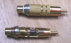
it's a premium kit with elna silmics and silver solder/ silver wires etc. with 2 inputs and one "rec out" - straight signal output without pot, also it will give the mute function to my amp in this position (i use the "rec out" with my headphone amp, then i dont need to connect the cables from sources directly to my headamp each time)
greets, ronald
hi,
a little showoff of my new gainclone
An externally hosted image should be here but it was not working when we last tested it.
it's a premium kit with elna silmics and silver solder/ silver wires etc. with 2 inputs and one "rec out" - straight signal output without pot, also it will give the mute function to my amp in this position (i use the "rec out" with my headphone amp, then i dont need to connect the cables from sources directly to my headamp each time)
greets, ronald
Re: my new gc
both the site and the amp look professional. hope it sounds as good as it looks.
rnzr said:
both the site and the amp look professional. hope it sounds as good as it looks.
Hello again, I an in the process of putting one of your DACs together and I have a few things I need to get sorted out. I got the bare PCB and no components and it is the L1-L4 thats causing my problems, there aren't any specs listed in the schematic, neither on the partslist.
So, could you tell med the values and tolerances on these four inductors?
And one more thing. C5a and C5b? There are only room for one C5 on the board.
The DAC in question
(I would send Damien a mail but no contactlink is specified, at least not when I checked a few minutes ago)
Kind regards
K.
So, could you tell med the values and tolerances on these four inductors?
And one more thing. C5a and C5b? There are only room for one C5 on the board.
The DAC in question
(I would send Damien a mail but no contactlink is specified, at least not when I checked a few minutes ago)
Kind regards
K.
kmj said:I got the bare PCB and no components and it is the L1-L4 thats causing my problems, there aren't any specs listed in the schematic, neither on the partslist.
Actually, when you check attached schematic, L1-L4 are marked as PLK1077 (Panasonic) and P9818 (Panasonic); those are DigiKey part numbers.
With a Green board you use only C5; C5a and C5b is with respect to all in one board where power traces are longer and two separate caps are being used.
Attachments
rnzr said:Actually yes, it sounds good as it looks
And it looks great indeed, congratulations!

Actually, when you check attached schematic,
I'll be...
It seems like the schems on my computer is missing some stuff.
I'll update them. And ofcourse, thanks
Peter Daniel said:Pin 13 can be grounded or not; in my board it's not.
Ok, thanks for your reply. Something new to experiment with!
Another question (it's been asked before but I can't find a clear answer): I want to place a led on my board to check if the signal is locked into the receiver. If it's locked, I want the led to go out. Is there a way to do that?
reMC said:I want the led to go out.
It surely can be done, maybe using transistor driving a relay?
However, why would you need it a LED; unless something is broken the DAC is always locked
- Status
- This old topic is closed. If you want to reopen this topic, contact a moderator using the "Report Post" button.
- Home
- More Vendors...
- Audio Sector
- AudioSector-chip amp kits, dacs, chassis