Final version with lightspeed attenuator
I worked all day Sunday on the lightspeed attenuator. It was pretty tedious work to test couplers to come up with two pairs with matching specs across the attenuation range. I installed it all and took a leap of faith by hard wiring onto the chipamp pcb without first testing the circuit.
Got a good night's sleep and then double-checked all my work with a clear head. With some trepidation, I hooked it up and powered up... whew. It came to life and sounds glorious.
I'm not an experienced audiophile, so I don't pretend to have all the critical vocabulary to describe the results, but my impressions follow so many other posts I have read but never personally experienced. There is a whole new level of sound on all my CDs. Soloists take a breath between notes. It's like they are alive and in the room with me. It's up close and personal now. At even modest volume I got a spooky feeling in my spine as notes kind of startled me. Bass is fully extended but controlled.
Drums are drums. Cymbals decay in the background as the music carries on. Bells and triangles ring as if they are in the room.
I played Dianna Krall. The placement of instruments is precise. Her voice is up higher than the piano and comes from deep BEHIND the stone wall of the fireplace that the amp is sitting on.
Again, hearing her breath is spooky.
The mechanical sound of the digital source has left. After an hour or so I realized that I was not listening to the stereo any more but was listening to the music. I figure this is what the whole goal is.
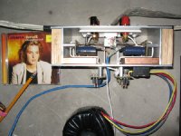
Here is a picture of the finished amp. The optocouplers are at the end of the blue cable and their signal leads are soldered to the input spots on the chip amp board. Their input leads go to the CATV via 3 fine silver wires on positive and one 24 gauge copper on negative. The blue cable goes to a separate power supply and cheap pot that acts as a dimmer switch for the LED’s to control the resistance of the photodiode. It was easy to wire in a balance control without losing any quality as it is not in the signal path, its in the dimmer circuit. So Cool!
I worked all day Sunday on the lightspeed attenuator. It was pretty tedious work to test couplers to come up with two pairs with matching specs across the attenuation range. I installed it all and took a leap of faith by hard wiring onto the chipamp pcb without first testing the circuit.
Got a good night's sleep and then double-checked all my work with a clear head. With some trepidation, I hooked it up and powered up... whew. It came to life and sounds glorious.
I'm not an experienced audiophile, so I don't pretend to have all the critical vocabulary to describe the results, but my impressions follow so many other posts I have read but never personally experienced. There is a whole new level of sound on all my CDs. Soloists take a breath between notes. It's like they are alive and in the room with me. It's up close and personal now. At even modest volume I got a spooky feeling in my spine as notes kind of startled me. Bass is fully extended but controlled.
Drums are drums. Cymbals decay in the background as the music carries on. Bells and triangles ring as if they are in the room.
I played Dianna Krall. The placement of instruments is precise. Her voice is up higher than the piano and comes from deep BEHIND the stone wall of the fireplace that the amp is sitting on.
Again, hearing her breath is spooky.
The mechanical sound of the digital source has left. After an hour or so I realized that I was not listening to the stereo any more but was listening to the music. I figure this is what the whole goal is.
Here is a picture of the finished amp. The optocouplers are at the end of the blue cable and their signal leads are soldered to the input spots on the chip amp board. Their input leads go to the CATV via 3 fine silver wires on positive and one 24 gauge copper on negative. The blue cable goes to a separate power supply and cheap pot that acts as a dimmer switch for the LED’s to control the resistance of the photodiode. It was easy to wire in a balance control without losing any quality as it is not in the signal path, its in the dimmer circuit. So Cool!
Attachments
optocoupler attenuator
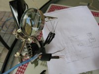
Here is the final pic. It's the attenuator under construction. A simple design following the design by georgehifi on this forum. Thanks George!
I used the version modified to include a balance control.
http://www.diyaudio.com/forums/showthread.php?s=&threadid=80194&perpage=10&pagenumber=59
My innovation was to wire it directly to the chip amp board. To facilitate this approach I simply glued two sorted couplers together rather than putting them on a separate board. I guess it reduces the flexibility of having a separate passive attenuator component, but my design goal is to produce a single integrated unit with all the characteristics of the best preamp, amp and DAC I can build on a budget. I don't plan to be changing components a lot, and I like the idea of one compact unit without a bunch of interconnects. I also came up with a rig to do the testing of all the optocouplers at once which took hours off the project. I'll post pics if anyone is interested.
Attachments
BNK said:Do you sell chassis (+connectors) only or chassis+transformer (+connectors)?
I have an old BrianGT 3875 kit that I never used because of missing the above.
I have no problem assembling/soldering so I don't need it assembled.
Thanks.
The chassis pictured here: http://audiosector.com/chassis_integrated.shtml is available as a kit at $250. All accessories are extra:
Brass cones $15/set
Knobs $18 ea.
Wooden sides $10 unfinished, $20 finished maple, $40 exotic wood
Shaft extenders $10/set
RCAs $3.50 ea
Cardas patented binding posts $35/set
Noble pot $22
Source selector $8 (different than pictured)
AC module $3
Plitron 300VA toroid $85
Re: CD Pro2 LF
I don't feel like changing anything in an existing DAC. It is complete product in a class of its own, and as such it's hard to improve any further.
There are certain mods that can still elevate performance, but that brings the price substantially higher: one can substitude Rikens for Caddocks TF020, use small value V-caps with a simple buffer at the output, and upgrade main filter caps to BG N or BG FK.
The DAC board can be placed in a CD player and some people actually do that.
jeffry_widjaja said:So peter ... would you like to build another DAC,
use Excellent board, best component (maybe opa 627bp,
BGN, low jitter cristal, best resistor, etc) and the board can
be place it in CD casing or separate
I don't feel like changing anything in an existing DAC. It is complete product in a class of its own, and as such it's hard to improve any further.
There are certain mods that can still elevate performance, but that brings the price substantially higher: one can substitude Rikens for Caddocks TF020, use small value V-caps with a simple buffer at the output, and upgrade main filter caps to BG N or BG FK.
The DAC board can be placed in a CD player and some people actually do that.
Re: Another Peter Daniel amp springs to life
Great work with quite unconventional approach")
wlowes said:Peter,
I am pleased to report that another of your kits has sprung to life and you have another very happy customer.
Great work with quite unconventional approach
Re: Re: CD Pro2 LF
What would be the main advantage of adding a buffer to the output, other than lowering the output impedence from 3K (it is 3K, right ?) to something much smaller ?
My current amplifier has an input impedence of 100k, so I figure a buffer wouldn't help much. However, I do plan on building an F3 soon, and since that has an impedence of about 10-20K, there may be some issues (I plan on using a passive preamp, probably a TVC, or something ...).
Peter Daniel said:
There are certain mods that can still elevate performance, but that brings the price substantially higher: one can substitude Rikens for Caddocks TF020, use small value V-caps with a simple buffer at the output, and upgrade main filter caps to BG N or BG FK.
What would be the main advantage of adding a buffer to the output, other than lowering the output impedence from 3K (it is 3K, right ?) to something much smaller ?
My current amplifier has an input impedence of 100k, so I figure a buffer wouldn't help much. However, I do plan on building an F3 soon, and since that has an impedence of about 10-20K, there may be some issues (I plan on using a passive preamp, probably a TVC, or something ...).
Re: Re: Re: CD Pro2 LF
While the pictures show the DAC assembled, it's mostly available as a kit, when one does assembly himself. On special requests, assembled version is available as well.
The main advantage of a buffer is lowering output impedance which may work better with following stages, especially when those have low input impedance.
The buffer will also allow to use smaller value of coupling caps. This matters mostly in case of premium parts, like teflon V-Caps. So instead of using $300/pc 2uF cap, one can get away with 0.1uF cap that costs "only" $50/pc
While the pictures show the DAC assembled, it's mostly available as a kit, when one does assembly himself. On special requests, assembled version is available as well.
lordvader said:What would be the main advantage of adding a buffer to the output, other than lowering the output impedence from 3K (it is 3K, right ?) to something much smaller ?
My current amplifier has an input impedence of 100k, so I figure a buffer wouldn't help much. However, I do plan on building an F3 soon, and since that has an impedence of about 10-20K, there may be some issues (I plan on using a passive preamp, probably a TVC, or something ...).
The main advantage of a buffer is lowering output impedance which may work better with following stages, especially when those have low input impedance.
The buffer will also allow to use smaller value of coupling caps. This matters mostly in case of premium parts, like teflon V-Caps. So instead of using $300/pc 2uF cap, one can get away with 0.1uF cap that costs "only" $50/pc
Unassembled DAC prices have been posted here: http://www.diyaudio.com/forums/showthread.php?postid=1170936#post1170936
More affordable sets are available as well, also USB version:
http://www.diyaudio.com/forums/showthread.php?postid=1195246#post1195246
More affordable sets are available as well, also USB version:
http://www.diyaudio.com/forums/showthread.php?postid=1195246#post1195246
Re: Re: Re: Re: CD Pro2 LF
How does one calculate the optimal coupling cap value (hence the rolloff).
For instance, given a 3K ouput impedence, I've currently got 0.47uF on the output, feeding a 100K input impedence.
Peter Daniel said:
The main advantage of a buffer is lowering output impedance which may work better with following stages, especially when those have low input impedance.
The buffer will also allow to use smaller value of coupling caps. This matters mostly in case of premium parts, like teflon V-Caps. So instead of using $300/pc 2uF cap, one can get away with 0.1uF cap that costs "only" $50/pc
How does one calculate the optimal coupling cap value (hence the rolloff).
For instance, given a 3K ouput impedence, I've currently got 0.47uF on the output, feeding a 100K input impedence.
Re: Re: Re: Re: Re: CD Pro2 LF
The formula can be found here: http://en.wikipedia.org/wiki/High_pass_filter
lordvader said:
How does one calculate the optimal coupling cap value (hence the rolloff).
For instance, given a 3K ouput impedence, I've currently got 0.47uF on the output, feeding a 100K input impedence.
The formula can be found here: http://en.wikipedia.org/wiki/High_pass_filter
Thanks for the link.
I've come across that formula, but I'm trying to understand how the source impedence comes into it.
You mention that using a buffer can enable the use of lower valued capacitors, but looking at the formula, you'll need a 0.8uF capacitor for a 20K amp, and corner frequency of 10Hz. How can a lower source impedence allow the use of something smaller ?
Sorry if these questions seem silly, but I've been unable to find a formula (or example), that takes the source impedence into accout.
I ordered them thru Allied.Algar_emi said:Where did you get the optocoupler for the lightspeed attenuator. Last time I check, they were very hard to get.
Thanks...
http://www.alliedelec.com/Search/Pr...ESC=NSL-32SR2S&R=699-3011&sid=46B90780C26617F
I am in Toronto. I placed the order on Monday, and they were delivered Thursday.
I ordered 8. They were all from the same batch and I got 3 matched pairs out of 8.
Poseidons Voice Anjali Amplifier
Well, she's finally come to life!
Front
Rear
Guts
400VA/22X2 Plitron transformers per channel. Lundahl 1676 input amorphous core trannies, wired so I get either 30dB or 24dB of gain, and many other goodies. For more info and pics look here
Thanks Peter ,
Anand.
Well, she's finally come to life!
Front
An externally hosted image should be here but it was not working when we last tested it.
An externally hosted image should be here but it was not working when we last tested it.
Rear
An externally hosted image should be here but it was not working when we last tested it.
An externally hosted image should be here but it was not working when we last tested it.
Guts
An externally hosted image should be here but it was not working when we last tested it.
400VA/22X2 Plitron transformers per channel. Lundahl 1676 input amorphous core trannies, wired so I get either 30dB or 24dB of gain, and many other goodies. For more info and pics look here
Thanks Peter ,
Anand.
- Status
- This old topic is closed. If you want to reopen this topic, contact a moderator using the "Report Post" button.
- Home
- More Vendors...
- Audio Sector
- AudioSector-chip amp kits, dacs, chassis