Peter Daniel said:Thanks Bob for clearing that up.
The DAC output section of my DAC is very similar to 47Labs DAC, which was measured by Stereophile: http://stereophile.com/digitalprocessors/800/index5.html
Thanks for the link!
Joshua
Hi Joshua,
I am quite sure that you aren't arguing, and I didn't intend to suggest that you were, which is why I said "with respect etc".")
I just wished to make it clear to you that in this particular case there is no question of "likely to be", it is the value of these shunt resistors which *determine* the output impedance of this DAC.
Basically, it is the impedance measured between the 'live' output terminal and ground (this is rarely the same as whatever is in series with the output, and it certainly isn't the same in this circuit), so in a straightforward case like this it is easy to determine simply by checking the schematic.
In truth, it will be a little lower than the exact value of the resistors used here, as there will be some much higher impedances in parallel with these resistors, within the TDA chip, itself, also referenced to ground. However for practical purposes, they will have very little effect on this output impedance in my opinion.
Anyway, I don't wish to hi-jack Peter's thread with this correspondence, but as I just saw your query when I was looking at this thread earlier and I had some time on my hands, I thought I might save Peter some trouble.
Regards,
I am quite sure that you aren't arguing, and I didn't intend to suggest that you were, which is why I said "with respect etc".
I just wished to make it clear to you that in this particular case there is no question of "likely to be", it is the value of these shunt resistors which *determine* the output impedance of this DAC.
Basically, it is the impedance measured between the 'live' output terminal and ground (this is rarely the same as whatever is in series with the output, and it certainly isn't the same in this circuit), so in a straightforward case like this it is easy to determine simply by checking the schematic.
In truth, it will be a little lower than the exact value of the resistors used here, as there will be some much higher impedances in parallel with these resistors, within the TDA chip, itself, also referenced to ground. However for practical purposes, they will have very little effect on this output impedance in my opinion.
Anyway, I don't wish to hi-jack Peter's thread with this correspondence, but as I just saw your query when I was looking at this thread earlier and I had some time on my hands, I thought I might save Peter some trouble.
Regards,
Bobken said:Hi Joshua,
I am quite sure that you aren't arguing, and I didn't intend to suggest that you were, which is why I said "with respect etc".
I just wished to make it clear to you that in this particular case there is no question of "likely to be", it is the value of these shunt resistors which *determine* the output impedance of this DAC.
Basically, it is the impedance measured between the 'live' output terminal and ground (this is rarely the same as whatever is in series with the output, and it certainly isn't the same in this circuit), so in a straightforward case like this it is easy to determine simply by checking the schematic.
In truth, it will be a little lower than the exact value of the resistors used here, as there will be some much higher impedances in parallel with these resistors, within the TDA chip, itself, also referenced to ground. However for practical purposes, they will have very little effect on this output impedance in my opinion.
Anyway, I don't wish to hi-jack Peter's thread with this correspondence, but as I just saw your query when I was looking at this thread earlier and I had some time on my hands, I thought I might save Peter some trouble.
Regards,
Hi Bob,
Thanks for the explanation! Ok, so the output impedance is the impedance seeing from the input of the stage after.
Yes agree, for practical purposes we'll take the lowest impedance which is the external resistor parallel with the DAC output, it should be close....and don't need to plot the output impedance across some range of frequency as well...
No such of hi-jack thing in my opinion, this is the beauty of the forum - learn from different perspective!
Regards,
Joshua
Hi Peter,
I hadn't seen your response when I started my last post (I got interrupted half way through writing it!) and I should apologise for my 'interference' in your thread.
I now see from your reference to Stereophile that their measurement was 2k3 for the 47 Labs version, and if they used this same 2k7 value as yours for the 2 shunt resistors concerned, this is rather lower than I would have guessed.
However, as I just said, any impedance to ground within the TDA chip's circuitry will have some effect on this issue, and needs to be considered in the equation as this will be effectively in parallel with these (output shunt) resistors in this case.
Next time, instead of saying "determined by" or "based on", I should remember to say "will be mainly determined by, or mainly based on".
Regards, and a happy Christmas to you and the family.
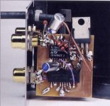
The 47Labs DAC is pretty close to this design: http://www.fedde.nu/audio/images/nonoz3.gif and if I'm not mistaken they use 3K resistors for I/V as in attached pic.
Happy Christmas
Happy Christmas
Attachments
Hi,
I seem to have dug myself into a bit of a hole here, so it will teach me to mind my own business in future!
The matter is a little more complex (isn't it always?) in that there will be variations at different frequencies (to satisfy Joshua's query), and strictly-speaking the output impedance should be stipulated at a particular frequency. This is why it is called output impedance, and not output resistance.
However for our purposes in a situation like this, it is basically what I have outlined, and few (including Stereophile, it seems) will even indicate at what frequency their measurements have been made, anyway.
This Fedde circuit is rather different as you have several extra caps and resistors in this part of the circuit which are not in Peter's, and these all have paths down to ground and will reduce overall impedances at certain frequencies as a result.
Regards,
Never give up!
Hi,
One final comment, if that pic of Peter's is a genuine 47 Labs Gaincard interior, then I for one am appalled at the constructional quality and layout.
Compared with anything you ever see of Peter's own work, that looks more as if it has been put together by a real amateur. Also, using parts 'flying in the air' like that is sometimes beneficial to keep certain signal-paths short etc., but this has hardly achieved anything worthwhile in this regard, if at all.
It just looks like a haphazard 'first-attempt' for an initial circuit-trial, like a prototype breadboard design.
Bobken said:Hi,
I seem to have dug myself into a bit of a hole here, so it will teach me to mind my own business in future!
The matter is a little more complex (isn't it always?) in that there will be variations at different frequencies (to satisfy Joshua's query), and strictly-speaking the output impedance should be stipulated at a particular frequency. This is why it is called output impedance, and not output resistance.
However for our purposes in a situation like this, it is basically what I have outlined, and few (including Stereophile, it seems) will even indicate at what frequency their measurements have been made, anyway.
This Fedde circuit is rather different as you have several extra caps and resistors in this part of the circuit which are not in Peter's, and these all have paths down to ground and will reduce overall impedances at certain frequencies as a result.
Regards,
Ok, 2k7 ohm is a good approximation of the output impedance
Thanks,
Joshua
joshuajoshua said:
Ok, 2k7 ohm is a good approximation of the output impedance
Thanks,
Joshua
You are very welcome.
Interestingly, if you add the 50k resistors at the output like Fedde's R9 & R10 (and I think Peter's PCB allows for these), this will lower the nominal output impedance from circa 2k7 to not much above 2k5 Ohms, with no other changes.
Regards,
Bobken said:
You are very welcome.
Interestingly, if you add the 50k resistors at the output like Fedde's R9 & R10 (and I think Peter's PCB allows for these), this will lower the nominal output impedance from circa 2k7 to not much above 2k5 Ohms, with no other changes.
Regards,
Ok, we can lower the output impedance by putting resistor in parallel at the output, 50k//2k7~2k5 ohms.
I keep this setup in mind just incase I need to match the impedance between stages
I don't have any experience with DAC, but wondering how low we can set the output impedance (using TDA1543) without changing the sonic signature significantly?
Thanks,
Joshua
Re: o/p impedance
That's right.
Joshua
mikelm said:every time you reduce the o/p impedance you reduce the o/p voltage
distortion should be better
mike
That's right.
Joshua
Hi Joshua,
I'm ducking out of this discussion now, as this is Peter's commercial thread which we are usurping rather, I did only get involved by accident, and I should be attending to other matters.
However, as you are seriously interested in this subject, you owe it to yourself to fully understand what is involved in these matters, as, regrettably, they are rarely quite as simple as at first they may appear. I don't wish to seem patronising here (and I still regularly learn something new about issues which I haven't thought much about before) but with a bit of searching, there is a wealth of information directly related to this subject, both on this Forum, and elsewhere on the 'Net. I am sure that you will find this very useful, and about 2-3 yrs ago, the subject was very fashionable, and occupied entire threads for a while.
IIRC, DDDAC (who is also a member here) has some very illuminating information on his site, and some graphs or charts relating to different loadings for these DACs, the effects on distortion, and the resultant output levels etc., and this might be a good starting-point if you haven't already seen this.
The difficulty in 'generalising' for brevity in a short response (as has just been proved!) is that there are nearly always other matters to consider when making any significant changes to established electronic circuitry. All such circuits are the result of a set of compromises which the designer has chosen, and, in improving (or changing) one parameter, it is quite usual that other parameters will worsen, unfortunately. There are 'no free-lunches' in life, nor in electronics, and it is therefore a good idea to become familiar with all of the related possibilities before contemplating any such modifications, or it is likely that the end-result will not be quite what is desired.
For example, as already mentioned, lowering the output impedance (which can be done to almost zero, by reducing R8 & R9 in Peter's circuit) will also reduce output levels, and will affect the distortion characteristics. Also, ideally the V-ref resistor (Peter's R7) will also most likely need to be changed in value, as this sets the centre-point of the output AC swing in relation to ground, and so on.
Somewhere on this Forum is (or was) an on-line calculator which you plug values into, and it will show the various relationships between rail voltage (which has a great effect on the distortion/sound characteristics), the values of the I/V resistors and V-ref resistor, and predicts the resultant output level etc. You might find this with a search, and it could also be useful to you.
Anyway, good luck with your endeavours.
Regards,
Here's the explanation how I/V resistors are calculated: http://www.diyaudio.com/forums/showthread.php?s=&postid=173483&highlight=#post173483
Bobken said:Hi Joshua,
I'm ducking out of this discussion now, as this is Peter's commercial thread which we are usurping rather, I did only get involved by accident, and I should be attending to other matters.
However, as you are seriously interested in this subject, you owe it to yourself to fully understand what is involved in these matters, as, regrettably, they are rarely quite as simple as at first they may appear. I don't wish to seem patronising here (and I still regularly learn something new about issues which I haven't thought much about before) but with a bit of searching, there is a wealth of information directly related to this subject, both on this Forum, and elsewhere on the 'Net. I am sure that you will find this very useful, and about 2-3 yrs ago, the subject was very fashionable, and occupied entire threads for a while.
IIRC, DDDAC (who is also a member here) has some very illuminating information on his site, and some graphs or charts relating to different loadings for these DACs, the effects on distortion, and the resultant output levels etc., and this might be a good starting-point if you haven't already seen this.
The difficulty in 'generalising' for brevity in a short response (as has just been proved!) is that there are nearly always other matters to consider when making any significant changes to established electronic circuitry. All such circuits are the result of a set of compromises which the designer has chosen, and, in improving (or changing) one parameter, it is quite usual that other parameters will worsen, unfortunately. There are 'no free-lunches' in life, nor in electronics, and it is therefore a good idea to become familiar with all of the related possibilities before contemplating any such modifications, or it is likely that the end-result will not be quite what is desired.
For example, as already mentioned, lowering the output impedance (which can be done to almost zero, by reducing R8 & R9 in Peter's circuit) will also reduce output levels, and will affect the distortion characteristics. Also, ideally the V-ref resistor (Peter's R7) will also most likely need to be changed in value, as this sets the centre-point of the output AC swing in relation to ground, and so on.
Somewhere on this Forum is (or was) an on-line calculator which you plug values into, and it will show the various relationships between rail voltage (which has a great effect on the distortion/sound characteristics), the values of the I/V resistors and V-ref resistor, and predicts the resultant output level etc. You might find this with a search, and it could also be useful to you.
Anyway, good luck with your endeavours.
Regards,
Hi Bob,
Appreciate for the advice.
You're right this subject is a little bit out of the subject, I guess I owe an apologize to Peter for starting the thing.
I just want to understand more about your comment of lowering the output impedance of DAC - if I need a buffer circuit to next stage in situasion where I can not match the impedance.
I'll search more info in some of the places that you suggested.
Thanks,
Joshua
Peter Daniel said:Here's the explanation how I/V resistors are calculated: http://www.diyaudio.com/forums/showthread.php?s=&postid=173483&highlight=#post173483
Thanks Peter!
Very useful information!
Joshua
xaudiox said:
Another one, thanks
Joshua
- Status
- This old topic is closed. If you want to reopen this topic, contact a moderator using the "Report Post" button.
- Home
- More Vendors...
- Audio Sector
- AudioSector-chip amp kits, dacs, chassis