For the supply I always use Cardas hook up wire, 20ga or so. It is stranded and enameled and requires solder pot for tinning/termination. For binding post connection I usually use Kimber or DH Labs, also stranded, 20ga.
For signal, it's always solid core, 26ga or so. Presently it's gold plated copper. For my best work I use silver.
For signal, it's always solid core, 26ga or so. Presently it's gold plated copper. For my best work I use silver.
Peter Daniel said:For the supply I always use Cardas hook up wire, 20ga or so. It is stranded and enameled and requires solder pot for tinning/termination. For binding post connection I usually use Kimber or DH Labs, also stranded, 20ga.
For signal, it's always solid core, 26ga or so. Presently it's gold plated copper. For my best work I use silver.
Thanks for the info!
Joshua
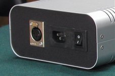
The fuse is accessible from the outside, you just need to remove fuseholder located in the power entry module: http://www.qualtekusa.com/catalog2/ac_recept/pdfs/76118003.pdf
I use 6A , slow blow fuse.
I use 6A , slow blow fuse.
Attachments
Can I use this together with Nuuk's GC preamp?
http://myweb.tiscali.co.uk/nuukspot/decdun/gainclonepre.html
http://myweb.tiscali.co.uk/nuukspot/decdun/gainclonepre.html
doomsweek said:Can I use this together with Nuuk's GC preamp?
If you mean the amp, yes, it should work with that preamp.
There is no price for it, as it's not my standard item. It can be easily built and the cost of the Elma switch is $60, Caddocks are $4 ea ($6 for lower values). Series Vishay is $12. All parts available from Percyaudio.
The steps can be calculated using attached calculator. It is recommended to use cheaper resistors for steps which are rarely used.
The steps can be calculated using attached calculator. It is recommended to use cheaper resistors for steps which are rarely used.
Attachments
Peter & all,
I just plugged in my premium DAC for the first time ..
So far so good - best feature so far - lovely natural mid band.
treble is a little less than normal but bass is firm & clear.
it seems to be passing the female vocal test ( which was the motivation for the change )
One question
This thing has many black gate caps - renowned for long burn in period
How long do we think it will be to reach full potential ?
thanks
mike
mikelm said:How long do we think it will be to reach full potential ?
Based on a customer feedback, it seems like the break in point is achieved after a month or so.
You can furhter adjust the highs by installing Caddocks TF020 in place of Rikens and switching to different coupling caps.
In order to use small value V-Caps (0.1uF or so, to save on cost) a simple Borbery buffer can be installed at the output with very good results (fig 15C): http://www.borbelyaudio.com/adobe/ae699bor.pdf
Hi,
I am sure Peter is referring to me here, but I must say that his buffer is excellent sonically, and it outperformed a commercial (Burson) buffer which I compared it with.
However, in the pursuit of perfection I did try other designs and the best I have come up with so far is based on the quite simple Borbely circuit mentioned.
This was constructed with the finest components available anywhere, like 2SK389 dual J-Fets, all Vishay bulk-foils & non-polar BGs etc., and complex discrete regs (actually of my own design, not ALW's).
This was a 'cost no object' exercise, and the advantage of this J-Fet circuit is that there are so few parts needed (apart from PS) so it it is not quite so frightening in parts costs as some more-complex alternatives.
In some respects it is preferable to my ears than Peter's Buffer, but if the same quality of parts were to be used for Peter's buffer circuit as I used in the J-Fet version, I wouldn't like to predict the outcome.
At this level of perfection, VHQ parts do make a worthwhile difference, but at a collossal additional cost of course, and it is possible that Peter's Buffer might equal (or even exceed) the J-Fet buffer's performance if the same parts were used throughout.
In my opinion, you will find it very hard to better Peter's design without spending considerably more than he charges for his kits, and there is (almost) always scope for improvements with any circuit if you are prepared to throw unlimited funds at the project.
Regards,
Bobken said:To save Peter the trouble, as I was looking at this thread anyway, it is based on the output (shunt) resistors to ground.
In Peter's design these are R8 & R9, which I believe are usually 2k7.")
Ok, that's most likely the answer
...Thanks,
Joshua
Hi Joshua,
With the greatest respect, it *is* the answer, or at least it is these resistors which determine the output impedance in this particular circuit.
No doubt Peter will confirm the values of resistors he uses here, but in the circuit which I am aware of he uses 2k7 for R8 & R9., and therefore the output impedance will be (approx) 2k7, allowing for any component variations.
Regards,
Bobken said:Hi Joshua,
With the greatest respect, it *is* the answer, or at least it is these resistors which determine the output impedance in this particular circuit.
No doubt Peter will confirm the values of resistors he uses here, but in the circuit which I am aware of he uses 2k7 for R8 & R9., and therefore the output impedance will be (approx) 2k7, allowing for any component variations.
Regards,
Hi Bob,
I'm not arguing, I'm just trying to understand what output impedance is in that DAC.
As we are talking about amp, in my understanding the output impedance (in series with the output) will determine the regulation of that amp.
The higher the output impedance, the less output voltage under the load.
As for the DAC (output I/V), I don't know much...
And yes, I looked to the schematic before post this thread and notice 2K7 ohm at the output for both left and right channel.
Just want to fulfill my curiosity and learn something...
Joshua,
Thanks Bob for clearing that up.
The DAC output section of my DAC is very similar to 47Labs DAC, which was measured by Stereophile: http://stereophile.com/digitalprocessors/800/index5.html
The DAC output section of my DAC is very similar to 47Labs DAC, which was measured by Stereophile: http://stereophile.com/digitalprocessors/800/index5.html
- Status
- This old topic is closed. If you want to reopen this topic, contact a moderator using the "Report Post" button.
- Home
- More Vendors...
- Audio Sector
- AudioSector-chip amp kits, dacs, chassis