Re: grounding scheme
I don't connect 0V from transformer to Earth ground, only PS chassis is connected to Earth ground.
The power ground in the amp is connected to the chassis through 10R resistor.
joshuajoshua said:I notice in your Patek Amp design, you put a chassis connection from the star point ground thru a small value resistor. I believe this is for safety reason in which it gets connected to the earth ground connection at separated power supply module...cmiiw..
That brings me to another different question, does the 0 volt point at secondary side of the transformer has always to be connected to the earth ground? Can we just leave it floating?
I don't connect 0V from transformer to Earth ground, only PS chassis is connected to Earth ground.
The power ground in the amp is connected to the chassis through 10R resistor.
Re: Re: grounding scheme
Ok, so 0 volt from transformer is floating refers to earth ground. Can you please help me to understand what is the purpose of connecting the power ground in the amp to its chassis thru 10R?
The reason being is I plan to build separate chassis for the amp (dual mono amp in 1 chassis) and the PS (using 2 transformer in 1 chassis). And yes, I think it's better to have the 0 volt power ground floated from the earth ground to avoid possible ground loop inside the system or with other equipment thru the outlet ground power. But on the other hand, I won't have safety feature just incase the hot voltage leaking thru amp chassis - as it is floating from the earth ground.
I think I will make a connection from PS chassis to amp chassis, in that way it provides the current path for any unexpected voltage in both chassis to be drawn to earth.
Can you give an opinion for this arrangement?
Thanks for the quick response..") ...
...
Joshua
Peter Daniel said:
I don't connect 0V from transformer to Earth ground, only PS chassis is connected to Earth ground.
The power ground in the amp is connected to the chassis through 10R resistor.
Ok, so 0 volt from transformer is floating refers to earth ground. Can you please help me to understand what is the purpose of connecting the power ground in the amp to its chassis thru 10R?
The reason being is I plan to build separate chassis for the amp (dual mono amp in 1 chassis) and the PS (using 2 transformer in 1 chassis). And yes, I think it's better to have the 0 volt power ground floated from the earth ground to avoid possible ground loop inside the system or with other equipment thru the outlet ground power. But on the other hand, I won't have safety feature just incase the hot voltage leaking thru amp chassis - as it is floating from the earth ground.
I think I will make a connection from PS chassis to amp chassis, in that way it provides the current path for any unexpected voltage in both chassis to be drawn to earth.
Can you give an opinion for this arrangement?
Thanks for the quick response..
...Joshua
I use 10R resistors to separate both grounds, you may use it, but it's not neccessary.
Connecting amp chassis with PS chassis to have Earth ground on both is a good idea and Patek has a bottom screw that allows it as well: http://audiosector.com/images/patek2/patek2_08.jpg
Connecting amp chassis with PS chassis to have Earth ground on both is a good idea and Patek has a bottom screw that allows it as well: http://audiosector.com/images/patek2/patek2_08.jpg
Peter Daniel said:I use 10R resistors to separate both grounds, you may use it, but it's not neccessary.
Connecting amp chassis with PS chassis to have Earth ground on both is a good idea and Patek has a bottom screw that allows it as well: http://audiosector.com/images/patek2/patek2_08.jpg
Ok, I think I can incorporate earth ground path thru amp power conduit (probably in the form of conduit shield - which can protect the amp power cable from RFI?) and screw it inside the amp chassis.
I guess I can still maintain the floating state for the amp, while having safety feature implemented
Thanks for the feedback Peter!
Joshua
Patek chassis was available to whoever asked about it. The price was approx $400 and it included input/output connectors and umbilical cord.
I'm down to 3 chassis at the moment and those are reserved for complete amps, but when the new batch is ordered that chassis may be available again.
I recently came up with an integrated version of the amp and it got very good response from the first customer:
BTW, Patek has been recently nominated as "Favourite Discovery of 2007" by one of the 6moons reviewer: http://www.6moons.com/industryfeatures/bo2007/stephaen.html
I'm down to 3 chassis at the moment and those are reserved for complete amps, but when the new batch is ordered that chassis may be available again.
I recently came up with an integrated version of the amp and it got very good response from the first customer:
An externally hosted image should be here but it was not working when we last tested it.
An externally hosted image should be here but it was not working when we last tested it.
An externally hosted image should be here but it was not working when we last tested it.
An externally hosted image should be here but it was not working when we last tested it.
An externally hosted image should be here but it was not working when we last tested it.
BTW, Patek has been recently nominated as "Favourite Discovery of 2007" by one of the 6moons reviewer: http://www.6moons.com/industryfeatures/bo2007/stephaen.html
Re: magnet wire
I have experimented with magnet wire and found it worked well. I followed a design posted elsewhere. A flat cable is made with clear packing tape keeping + & - wires 1/2" apart. I used 24 gauge on the neg and 2 strands of 28 on the pos. It was simple and sounded better than anything previous. Strip the enamel with little fine sand paper.
Since then I have built cables using the same architecture but much better wire. Another big step forward. I now use pure 24 gauge silver on the neg and 3 strands of 30 gauge on the pos. 2 strands are silver and one fine gold. This cleared up distortion in the high end that comes with copper. The gold added warmth. Pretty hard to justify the cost of gold. ($10/foot) I am sure silver is almost as good at a fraction the cost. The silver wire is dirt cheap at www.myrontoback.com. Great info on cable design at http://forum.audiogon.com/cgi-bin/frr.pl?rcabl&1150905409&read&3&4&.
For me the results are well worth it. Just finished adding Peter's USB DAC to the chip amp using these cables. Nothing could be finer.
joshuajoshua said:Does anybody have any experience of using magnet wire for interconnection for gainclone amp in particular ...or for any amp in general?
Joshua
I have experimented with magnet wire and found it worked well. I followed a design posted elsewhere. A flat cable is made with clear packing tape keeping + & - wires 1/2" apart. I used 24 gauge on the neg and 2 strands of 28 on the pos. It was simple and sounded better than anything previous. Strip the enamel with little fine sand paper.
Since then I have built cables using the same architecture but much better wire. Another big step forward. I now use pure 24 gauge silver on the neg and 3 strands of 30 gauge on the pos. 2 strands are silver and one fine gold. This cleared up distortion in the high end that comes with copper. The gold added warmth. Pretty hard to justify the cost of gold. ($10/foot) I am sure silver is almost as good at a fraction the cost. The silver wire is dirt cheap at www.myrontoback.com. Great info on cable design at http://forum.audiogon.com/cgi-bin/frr.pl?rcabl&1150905409&read&3&4&.
For me the results are well worth it. Just finished adding Peter's USB DAC to the chip amp using these cables. Nothing could be finer.
Re: Re: magnet wire
Interesting design!
How do you make a reliable connection at the RCA(?) connector?
Can you share some of your pictures?...it will represent thousand of words.....
Thanks!
Joshua
wlowes said:
I have experimented with magnet wire and found it worked well. I followed a design posted elsewhere. A flat cable is made with clear packing tape keeping + & - wires 1/2" apart. I used 24 gauge on the neg and 2 strands of 28 on the pos. It was simple and sounded better than anything previous. Strip the enamel with little fine sand paper.
Since then I have built cables using the same architecture but much better wire. Another big step forward. I now use pure 24 gauge silver on the neg and 3 strands of 30 gauge on the pos. 2 strands are silver and one fine gold. This cleared up distortion in the high end that comes with copper. The gold added warmth. Pretty hard to justify the cost of gold. ($10/foot) I am sure silver is almost as good at a fraction the cost. The silver wire is dirt cheap at www.myrontoback.com. Great info on cable design at http://forum.audiogon.com/cgi-bin/frr.pl?rcabl&1150905409&read&3&4&.
For me the results are well worth it. Just finished adding Peter's USB DAC to the chip amp using these cables. Nothing could be finer.
Interesting design!
How do you make a reliable connection at the RCA(?) connector?
Can you share some of your pictures?...it will represent thousand of words...
..Thanks!
Joshua
Peter Daniel said:If your source has low output impedance, 10k should work fine.
If not, 50k is not a problem either, as input shunt resistor (22k) is parallel with potentiometer and takes care of higher impedance of the pot.
I'm still using 50k pots in AMP-1 and they work very well.
Peter,
What would be the best pot value to put between your USB DAC and gainclone?
Could share your knowledge, why it's better to have low impedance input amp when the driver has low output impedance?
Is it matching impedance? or is there any other reason for this particular setup?
Thanks,
Joshua
joshuajoshua said:What would be the best pot value to put between your USB DAC and gainclone?
Could share your knowledge, why it's better to have low impedance input amp when the driver has low output impedance?
Is it matching impedance? or is there any other reason for this particular setup?
As the DAC has pretty high output impedance, probably 50k pot would be best.
If your source has low output impedance I prefer to keep series resistance low, that's why low value pot. Also, lower input impedance will keep the DC offset low, with my amps.
Peter Daniel said:
As the DAC has pretty high output impedance, probably 50k pot would be best.
If your source has low output impedance I prefer to keep series resistance low, that's why low value pot. Also, lower input impedance will keep the DC offset low, with my amps.
Thanks for the explanation!
Do you have a USB DAC kit available?
Joshua
Peter Daniel said:Yes, USB DAC is available.
Ok, i follow up with email, thanks.
Joshua
The Patek Integrated
Hi Peter,
I really admire your skills! (and envy them too).
How do you managed to bend the LM3875 chips so that no legs were broken?
Is it possible to ask for a photo of the underside of the amp so that the power cord connection is visible? Do you have photos of the power supply too?
Thank you!
Best wishes
Jan Ove Tangen
Bending the pins is not a problem, they never break.
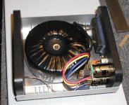
Here's the picture of the underside:
The PS as in attachment.
Here's the picture of the underside:
An externally hosted image should be here but it was not working when we last tested it.
The PS as in attachment.
Attachments
- Status
- This old topic is closed. If you want to reopen this topic, contact a moderator using the "Report Post" button.
- Home
- More Vendors...
- Audio Sector
- AudioSector-chip amp kits, dacs, chassis