Hello Bob,
Long time no hear.
Nice to see you are getting such good results with my old shunt regulator design though I have moved it on considerably in performance over the last few years. It now has a much wider operating bandwidth, faster transient response and settling time, lower noise and lower output impedance over a much wider bandwidth.
Regards
Paul
Hi Paul,
You must be referring to the rather basic shunt regulator which I developed and which (eventually after a plea for help) I commented-on in this thread, and also subsequently suggested a few other possible changes together with some cautionary advice for the unwary. Of course, regulator topology similar to this is hardly unique as it merely requires 2 basic 'text-book' regions, one to restrict the current passing and the other (based on well-known op-amp circuitry) to keep the output-voltage constant. My own first trials 'in the very early days' were with a schematic I found on the Internet which was identical in overall layout except for using a different current source and a bipolar instead of a mosfet to stabilise the output voltage.
As Peter knows (having been kept up-to-date with my trials) I finally abandoned this early shunt version for this DAC because I was unable to get it to sound as good in this DAC environment as I wished, and I went back to experimenting with alternative regulator ideas for a while.
Being in my 70's now and suffering from short-term memory-loss on occasions, I don't recall precisely what inspired me to return to this simple shunt layout subsequently, but I have been influenced by Erno Borbely's writings and more significantly by the very extensive articles on discrete regulators by Walt Jung in AudioXpress and on his site. Walt kindly shared a wealth of information, measurements, and advice on both series and (more-recently) on shunt regulators - and recommended the use of (the unfortunately 'all-too-rare' choice of) depletion mosfets for current-regulation duty.
My late mentor John Linsley Hood would often say "there are very few entirely new circuits being designed in the world, and acclaimed new ideas are nearly always re-hashes of something which went before, even though the 'new' designer might not always be aware of this". In the case of DIY circuits like we are dealing-with here, it is probably almost inevitable that for our own use we end-up replicating ideas, concepts, and topologies that have been seen in the past, and even the entire concept of this type of DAC with no output filtering originated from others like Kusunoki and Audionote, I understand.
Personally, I have never been an imaginative nor creative designer as I have previously admitted on this Forum, but with having JLH as a friend and mentor for so many years before his death, I didn't need to be. This is why whenever I share any results of experiments which I have found to be sonically good, I generally refer to them as 'developments' and not to 'my designs', because almost universally whatever I get involved with will have been initially sparked-off by seeing someone else's ideas, or perhaps a data-sheet, or whatever else in the way of other circuitry.
Accordingly, I have gone to great lengths to give credit to all of those enthusiasts before me who worked on this NOS DAC concept for many years before I even became interested in it. As I have already acknowledged, it is they (including Peter) who clearly 'pioneered' this type of circuit and produced such extraordinary results, which (when I first heard them over 5yrs ago) inspired me to see what I might be able to do myself to add to this excellence.
However, having spent a lifetime modifying and (hopefully) improving some of the circuit ideas of others (in JLH's case always with his full encouragement and help) I believe I have rather proved his unerring contention. This being that it is the *implementation* of these basic circuit-blocks which is just as important as the overall topology, and for a large part I have found that this comes down to the very careful choice of individual components decided through painstaking listening-trials. This was not intuitive initially to JLH, but after visiting me on several occasions he was pleased and surprised with what he heard.
As the years have gone by I became less concerned with measurements although I do still measure results wherever I can, but nowadays I tend to rely mainly upon empirical trials, and this seems to stand me in quite good stead for most of the time.
Being retired for some years I am now obliged to use whatever components I still have in stock for many of my recent modifications/experiments, because the passive parts that I do specially need to purchase are often rather costly, and hence I always favour circuits with the fewest-possible individual components used in them. Actually, I cut my 'audio-electronics teeth' in the 1970's by working mainly on JLH's well-known and still highly-revered amplifier circuits, often by completely eliminating certain components and entire regions which didn't seem so vital to me at the time, and my results influenced the original designer's future circuits after he had listened to the sonic benefits I had demonstrated. This was in spite of the fact that in most instances the measured-results were actually often less-good, but, with fewer components involved, there is less to 'optimise' and less to get wrong which might adversely affect the sonic performance.
You suggest that my 'final version' of this shunt reg is the same as (or similar to) one of your own earlier designs, which is slightly surprising because it took me nearly 4 yrs of experiments and many changes made over time to the original circuit-concept which I had commenced-with, before I was finally satisfied with the overall sonic results. If your "old shunt regulator design" circuit is the same as the version posted here, perhaps I should feel a little flattered that at least one other member (apart from Peter and his associates) has found this circuit to be quite good, at least for this particular DAC's PS requirements.
My final implementation constructed exactly as shown just appears to have some particular synergy with the TDA1543 NOS DAC and it is the best I have yet tried out of a number of variations, but I have also mentioned several times in this thread before that it is far from being a sophisticated or ideal design/implementation IMO for general usage. I have clearly pointed-out the several obvious limitations it has, and have stated that I would not use such a relatively simple circuit with this performance in any highly-demanding circuitry like perhaps phono amps etc., which has been asked about by others on this Forum more than once here since Peter first posted the schematic.
Incidentally, I don't look at audio fora (including this one) much these days, but my attention was recently drawn to some derogatory remarks in a 'rival' forum about my implementation of this regulator, so I now feel more-encouraged that if your version is (or rather was) the same, at least it is not my imagination that it does sound rather good. Anyway, I didn't pay too much attention to those criticisms because to me it still sounds great (and so it does to the others who have heard it) in this particular application. Also, one adverse comment I still recall from this poster was that I was using a mosfet well-outside of its thermal-limits, whereas in practice the device in use is not even warm to the touch!
Needless to say, this brief but destructive posting failed to point-out (unlike what I have honestly and openly said in this thread) some much more-consequential matters and that (by force of circumstances) I am using some devices well outside of the device-maker's recommendations, although never intentionally in an *unsafe* manner nor in one which is likely to result in excessive or dangerous heat-production etc.
I don't for one moment doubt that (as you seem to have found recently) almost any regulator concept like this can still be improved to provide superior measurements, and any such circuit-block can usually benefit from further development effort in the light of longer-term experience in use. This is why I encourage others to experiment for themselves - so long as they are not getting right outside of their 'comfort-zones' and ending-up with drastic failures.
Whether any results of these further experiments (either by me, or by anyone else) will improve the *sound* of this DAC any further or not, remains to be seen. I am still working on it!
Regards,
bobken and Paul,
Can the shunt regulator be used at 3.3V.....and, if so, what values need changing? Can the 811 operate that low?
Thanks
Hi Ric,
It looks like Paul has already answered this query of yours before I saw your question, but it may help you to look at my posting #85 which gives a little more background and explanation in this connection.
Regards,
buzzforb
The BSS129 is functioning as a current source and the AD811 is controlling the shunt element ZVN3310.
Peter,
I hope you are not offended if I continue to post on this regulator topology. Now that the regulator circuit has been released I feel I should help people with the application of this circuit.
Regards
Paul
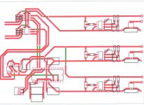
Finally getting around to finsihing Dac and had some questions. What are alternatives for the Blackagates used in the circuit. I have MKP1837 in those values, but have read that FM and FC mat be preferred. Until i listen for a while, I cannot justify the steep prive for sized blackgates. Here is my DIY PCB, doesn't include prefilter, psu output caps, or dac output caps. They will be added. THought someone might want to help double check or offer routing advice. Single sided is probably best i can do without suggestion.
Attachments
There is no real "alternative" to Black Gate, unfortunately. For me, the "second best" in digital are Sanyo Os-Con or Elna Starget (Stargets being mellower and more pleasant of the two, but slightly less precise).
The PCB looks nice and orderly, but is kinda hard to read without any part names... What is the 14-pin IC on the far left?...
The PCB looks nice and orderly, but is kinda hard to read without any part names... What is the 14-pin IC on the far left?...
I use TOCO toggle switch for source selecting, didn't observe any problems.
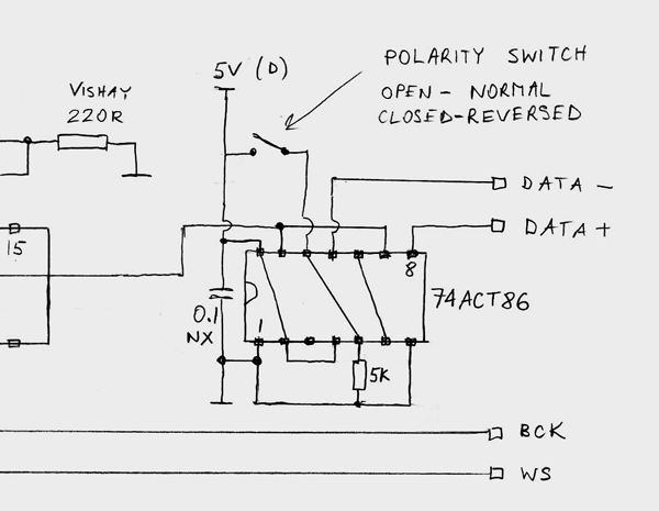
As to polarity switch, this is how it's implemented (to match my reversed XLR output wiring, for unbalanced signal, it will be the other way)
Hi Peter, I think this is interesting, but I cant find this part. I am looking to get a balanced out to drive a long line (from digital TV to stereo amp). I understand this is to get one chip to reverse the signal in polarity. One TDA1543 gets DATA+ the other DATA- signal.
Do you have a source or ref of it?
albert
Can it be the 74AC86?
Being a Quad 2-Input Exclusive-OR Gate?
The 'AC' series is normal CMOS (i.e. symmetrical) logic levels and the 'ACT' is TTL-compatible logic. Since the source is a CMOS part either should be OK from a technical pov. I don't know if Peter's auditioned one over the other though.
For myself I prefer to use the 'HC' family as it generates much less switching noise. In driving my own TDA1543 DAC I run the part (74HC86) from a TL431 shunt regulator at 2.5V to keep the edges nice and gentle
")
Its similar, not identical because I have no use for the phase invert switch. I have a switch but its used to check the balance of the two (positive and negative) sides. So in mine there's a 'normal' position and a 'test' position where there should be nothing coming out if all is correctly working This means I'm only using two gates for data, I use the other two to buffer BCK and WS.
@buzzforb - thanks for asking I've graduated up from TDA1543 to TDA1545 now that I have a way to solve the latter's glitchiness. For a long time, 1543 sounded best but just in the last month, 1545 has overtaken it for me. I guess I'll write it up on my blog sometime...
This means I'm only using two gates for data, I use the other two to buffer BCK and WS.@buzzforb - thanks for asking
I've graduated up from TDA1543 to TDA1545 now that I have a way to solve the latter's glitchiness. For a long time, 1543 sounded best but just in the last month, 1545 has overtaken it for me. I guess I'll write it up on my blog sometime... - Home
- More Vendors...
- Audio Sector
- Pushing the limits of TDA1543 NOS DAC