I am currently putting together an Audiosector lm4780 dual mono amp, 2 transformers and 2 PSU boards, is it recommended to create some kind of star ground between the psu boards and the amp boards?... meaning do I need to take all the negative connections to a single ground point on the metal chassis?
Also would I need to connect the speaker negative's to this ground star as well?
Also would I need to connect the speaker negative's to this ground star as well?
Hi, If you have dual transformers then I would not do as you have suggested. I assume that the PS boards have a zero volts point, this is where your star ground for each channel should be (assumption as I have not seen the pcbs for the amps or ps, (some of the kits have separate +v and -ve zero volts points).
Certainly run the saftey earths to the same point on the chassis, but whether or not this comes from the PS star point I couldn't say without seeing the design.
I would personally run the speakers negative to the star points directly but again it depends a bit on the pcb designs of the audiosector PCB's (do they have a speaker negative point on the amp pcb?).
I believe that If you tie the separate channels zero-volts together you will lose some of the benefit of having dual mono, and you will get increased crosstalk between channels.
Tony.
Depends on the voltage. You need to take measures against direct contact, if the voltage at the speaker terminals can reach or exceed 60 V DC (unlikely) or 25 V AC (possible depending on the transformer).
Then you have the choice between class I style and class II style. Class II style means to double-insulate all conductive parts. For speaker terminals and wires that is pretty impractical. So you'd rather use class I style which means to connect one end of the output, here the negative pole, to the chassis and install fuses in the rails that blow in case of a short to case. Once you do that and you have the chassis connected to PE, because you also did a Class I layout for the mains voltage, you have little choice but to create a star-ground to avoid ground loops.
Then you have the choice between class I style and class II style. Class II style means to double-insulate all conductive parts. For speaker terminals and wires that is pretty impractical. So you'd rather use class I style which means to connect one end of the output, here the negative pole, to the chassis and install fuses in the rails that blow in case of a short to case. Once you do that and you have the chassis connected to PE, because you also did a Class I layout for the mains voltage, you have little choice but to create a star-ground to avoid ground loops.
I seem to recall that AudioSector gives details and pics of exactly how to do the grounding.
They even show an alternative that allows for the use of a non recommended transformer.
Have you read? :
http://www.diyaudio.com/forums/diya...udio-component-grounding-interconnection.html
They even show an alternative that allows for the use of a non recommended transformer.
Have you read? :
http://www.diyaudio.com/forums/diya...udio-component-grounding-interconnection.html
In reply to wintermute this is the PS board http://www.audiosector.com/lm4780 psu.pdf
In reply to AndrewT, I did spend quite some time looking over previous posts on here and most only show a setup with a single transformer, i couldn't find anything relating exactly to what I want to do
In reply to AndrewT, I did spend quite some time looking over previous posts on here and most only show a setup with a single transformer, i couldn't find anything relating exactly to what I want to do
I am currently putting together an Audiosector lm4780 dual mono amp, 2 transformers and 2 PSU boards, is it recommended to create some kind of star ground between the psu boards and the amp boards?... meaning do I need to take all the negative connections to a single ground point on the metal chassis?
Also would I need to connect the speaker negative's to this ground star as well?
I assume you are using a single chassis.
There is no need for any additional star ground in case of dual mono setup, as each amp pcb features on board star ground.
The earth ground from power entry module connects directly to chassis and each amp board connects to the same ground point as well (run wires from CHG pads).
BTW, using rail fuses with LMXXXX chip amps is a bad idea; in case only one fuse blows, an excessive DC offset may occur and damage your speakers.
Yes I am using a single chassis.
Where abouts are the CHG pads on the lm4780 boards, I just had a look but can't see them?
Indeed, I forgot I didn't marked them there.
The OG pad (output ground) is dual hole; use one of those for chassis ground.
Excellent thanks
") will I need to lift the ground with a resistor when connecting those pads to the chassis?
will I need to lift the ground with a resistor when connecting those pads to the chassis?Excellent thanks
Looks like Peter has sorted your problem
Just on the resistor, the only time that one would contemplate doing this is when there is a problem with earthloops, However simply adding a resistor is not a safe way to deal with it. Use of an earthloop breaker as shown in this article by Rod Elliot Earthing (Grounding) Your Hi-Fi - Tricks and Techniques is a much safer way to deal with the problem (if indeed there is one). If the other equipment you are connecting to doesn't have a safety earth (ie double insulated equipment of a commercial nature) then you shouldn't run into earth loop problems.
Tony.
BTW, using rail fuses with LMXXXX chip amps is a bad idea; in case only one fuse blows, an excessive DC offset may occur and damage your speakers.
Using no fuses is an even worse idea. Everywhere in the world the use of fuses is obligatory by safety regulations.
If the output stage blows, there will also be an excessive DC offset. That is why decent amplifiers have decent DC protection.
Using no fuses is an even worse idea. Everywhere in the world the use of fuses is obligatory by safety regulations.
If the output stage blows, there will also be an excessive DC offset. That is why decent amplifiers have decent DC protection.
And why the assumption that there is no fuses?
A properly selected fuse on transformer's primary always worked for me. This is also what I see implemented in other manufacturers decent amps.
Can you present a case example where rail fuse is superior to transformer primary fuse and situation where blown rail fuse creates less damage than blown primary fuse in case of LMxxxx chip amp with speakers connected?
And why the assumption that there is no fuses?
There are obviously none behind the secondaries.
A properly selected fuse on transformer's primary always worked for me. This is also what I see implemented in other manufacturers decent amps.
An amplifier that does not comply with elementary safety regulations can never be decent.
Can you present a case example where rail fuse is superior to transformer primary fuse
Fuses behind the secondaries are chosen according to the transformer’s nominal output current. They protect the transformer from overload (current that is only slightly higher than the nominal current for an extended time) and short-circuit (current that is much higher than the nominal current even if only for a short time).
Primary fuses must be oversized to 1,5-3 times the nominal current to withstand the inrush current. They can only safely protect the transformer against shorts in the primaries. They may protect the transformer against some shorts with low enough impedance behind the secondaries. Other shorts with not low enough impedance and certain overload situations will however not trip the primary fuse(s).
The workaround to use an inrush current limiter can only partly improve the function of the primary fuses. It can be shown that there are still situations possible where even a right-sized primary fuse won’t blow in spite of a fault on the secondaries, due to the damping effect of the windings and transformer losses. In fact I had to do such calculations during my formation time, so I can assure you that skipping the secondary fuses is a bad idea, just as bad as putting them anywhere else than right behind the secondaries. They don’t belong behind the rectifiers, smoothing caps or wherever else you sometimes see them, but directly behind the transformer secondaries.
and situation where blown rail fuse creates less damage than blown primary fuse in case of LMxxxx chip amp with speakers connected?
A blown fuse does not create any damage. The damage will rather be created if the primary fuse fails to blow when a secondary fuse would have blown (see above). And with a decent DC protection in place even an inadequate or non-working undervoltage protection in the chipamp will lead to no harm when only one rail fuse blows.
Those are certainly all valid points and thanks for the input. I don't mind if people fuse the amps in any possible way, including speaker's output, if that makes them feel better.
As pointed out, calculating proper fuse value may be tricky, and that's one area where secondary fuses in a chip amp can be risky, if not only for a reason that when improperly chosen it can blow without actual fault condition and that can damage the speakers.
And talking about decent (sounding) amps without rail fuses, here's a link to one such example: 6moons audio reviews: FirstWatt F5
As pointed out, calculating proper fuse value may be tricky,
Not at all. The transformer's nominal secondary current determines the fuse rating. A slow-blow characteristic is good enough for that task. The next higher current rating is sufficient, if the nominal current does not coincide with an available fuse rating. A smaller fuse is proof of having wasted money on a too big transformer.
The important thing is that those fuses are there to protect the transformer, nothing else. It is not possible to protect the amp or its components with fuses. That can only be done by electronic protection systems and thermal limiters, if at all.
More discussion on secondary fuses here: http://www.diyaudio.com/forums/chip...er-supply-beginners-guide-32.html#post2545322
Need a little help.
It took me forever to find this quote. The quote pretains to LM4780, but I assume it applies to LM3875 as well.
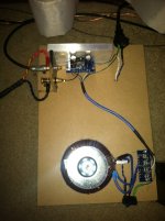
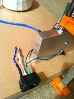
What if I will have 4 chassis? 1 chassis left amp, 1 chassis left power supply, 1 chassis right amp, 1 chassis right powersupply. Right now on 2 peices of wood, but will be moved to nice seperate 4 x chassis after I make it all work right.
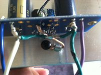
I think this photo of my first amp build must be how "not to do ground for dual-mono". I ended up with a little buzz in the speaker. I guess I was over thinking it, and got confused between dual-mono and stereo grounding layouts.
So I should unsolder this, then move my earth connection to CHG, connect PG+ / PG- to board directly, and no need to worry about any other star ground, is that right?
Any other things I need to do differently, because I have seperated the rectifier and amp boards. I'm specifically looking for how to build an embellical cord between the two chassis.
Thanks for all the help and support. I feel like I'm almost there.
Sincerely,
AlexQS
I assume you are using a single chassis.
There is no need for any additional star ground in case of dual mono setup, as each amp pcb features on board star ground.
The earth ground from power entry module connects directly to chassis and each amp board connects to the same ground point as well (run wires from CHG pads).
BTW, using rail fuses with LMXXXX chip amps is a bad idea; in case only one fuse blows, an excessive DC offset may occur and damage your speakers.
It took me forever to find this quote. The quote pretains to LM4780, but I assume it applies to LM3875 as well.
What if I will have 4 chassis? 1 chassis left amp, 1 chassis left power supply, 1 chassis right amp, 1 chassis right powersupply. Right now on 2 peices of wood, but will be moved to nice seperate 4 x chassis after I make it all work right.
I think this photo of my first amp build must be how "not to do ground for dual-mono". I ended up with a little buzz in the speaker. I guess I was over thinking it, and got confused between dual-mono and stereo grounding layouts.
So I should unsolder this, then move my earth connection to CHG, connect PG+ / PG- to board directly, and no need to worry about any other star ground, is that right?
Any other things I need to do differently, because I have seperated the rectifier and amp boards. I'm specifically looking for how to build an embellical cord between the two chassis.
Thanks for all the help and support. I feel like I'm almost there.
Sincerely,
AlexQS
Attachments
Last edited:
Buzz is gone
Hi, not sure if anyone is here...
If it helps any new guy out there to know, when I heard the buzz I instantly assumed it was a ground problem.
It turned out to be that anytime I connected the Coax CATV line from my cable company to my TV, in the vicinity of the amps that the TV would leak RF and make my speakers buzz.
It was a lot of deductive reasoning, and some nice guys on the diyAudio forum were very helpful to me. My first build, and now that the buzz is gone, it's the best sounding amp I have ever owned! Very open, detailed, good imaging, and depth. The bass is very solid, and I only have 10uF on the ps. They are driving what I think of as a heavy load, a 3-way Transmission Line speaker. The little LM3875 with a big powersupply is doing a great job.
I'm sure I'll build another one. Not sure what to try next though.
Later!
AlexQS
- Status
- This old topic is closed. If you want to reopen this topic, contact a moderator using the "Report Post" button.
- Home
- More Vendors...
- Audio Sector
- Audiosector lm4780 dual mono grounding