I think I am using a 1.6A with my 22v 300va. It has been in there for a number of years now. That may suggest it is over rated for my setup. Cricklewood Electronics have everything you will need.
Cricklewood Electronics - CCTV. CCTV Equipment. CCTV Systems. Digital CCTV Cameras
You will see others say you need a soft start, you may be better to keep your options simple to start with.
John
Cricklewood Electronics - CCTV. CCTV Equipment. CCTV Systems. Digital CCTV Cameras
You will see others say you need a soft start, you may be better to keep your options simple to start with.
John
This is the LED i intend to use on rectifier board... I have a nice Optic fibre kit that will let me put a blue power light on the front panel.
Can anybody help with what resistor it will need. Transformer is 300VA 2x22v. Dont wanna solder one in to have it blow on me.
http://www.vcclite.com/Customized/Uploads/SpecSheets/VAOL-3GWY4.pdf
Can anybody help with what resistor it will need. Transformer is 300VA 2x22v. Dont wanna solder one in to have it blow on me.
http://www.vcclite.com/Customized/Uploads/SpecSheets/VAOL-3GWY4.pdf
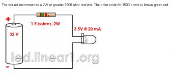
Transformer is rated in AC volts, after rectification you can expect approx 32V DC per rail and that's what you use for calculations. This is what you get:
If you find diode too bright, you can further increase resistance (and that's what I always do). I'm using 64k resistor with a small Panasonic red LED.
If you find diode too bright, you can further increase resistance (and that's what I always do). I'm using 64k resistor with a small Panasonic red LED.
Attachments
Last edited:
This is the LED i intend to use on rectifier board... I have a nice Optic fibre kit that will let me put a blue power light on the front panel.
Can anybody help with what resistor it will need. Transformer is 300VA 2x22v. Dont wanna solder one in to have it blow on me.
http://www.vcclite.com/Customized/Uploads/SpecSheets/VAOL-3GWY4.pdf
The larger size resistor you use, the dimmer the LED will be. They can be extremely bright so when I'm building guitar pedals, I usually start around 1K-2K and work my way up until it looks about right. Since you are dealing with much different voltage in these power supply boards, you should start with Peters recommendation of 62K and adjust from there. A lower value (say 50K) will make it brighter, a higher value (say 80K) will make it dimmer.
")
Last edited:
I have some single solid core wire i have been using in breadboard... Will this be thick enough to use for the dc power from rectifier to amp?
I am currently stripping the rubber from an old pc psu to cover the silver signal wire.. I'm using 0.60mm silver plated copper for the input and outputs, but stripping the rubber is killing me. I know you can buy it, but i'm an unemployed guy so money is tight.
Managed to get some samples of plastic bolts, nuts and washers for fixing amp chip to heatsink so i dont need to worry about shorting it. That said I have no intention of turning it on until i have tested everything at least twice.
Wire info... Overall diameter is 1.2mm, rated at 1.8A, 1kV
I need to connect my pot to front panel... I need a 5-6mm hole for threaded part and a 15-17mm countersink to take the fixing nut.
I have a hand power drill and a router, neither of which I am great with, but i gotta go for it. Anybody got any good tips on getting the holes nice and lined up. The hand drill is a no go... I hit 30 degrees going through 2mm, so 10mm is gonna be a bugga. Anybody used a router to do drilling and countersinking before. Is it possible?
I have a hand power drill and a router, neither of which I am great with, but i gotta go for it. Anybody got any good tips on getting the holes nice and lined up. The hand drill is a no go... I hit 30 degrees going through 2mm, so 10mm is gonna be a bugga. Anybody used a router to do drilling and countersinking before. Is it possible?
Got everything put together...Amps all wired to ins and outs...All grounds connected.
Not attached any power yet, just got wires ready to connect to rectifier. Got kettle lead socket with 2Amp fuse on live wire. Connected transformer to mains via block connectors, but not connected to rectifier yet.
Just need front panel drilling and countersinking to take power button, volume control and LED. Next step is test it as I go and connect power to each part.
Got front panel sorted... LED litepipe to get LED glow from rectifier to front panel, used a hot glue gun to fix it in place.
Volume control fitted with meccano, crude but its solid. Just gotta attach wires from amp ind inputs to it. Might get some small connectors for that.
Power button fitted and working... Stolen from a graphic equaliser, with a button from a sony amp.
Powered up transformer and tested output. Getting 24.5 volts from each. I was expecting a hum from it, but its silent. More importantly the fuse didnt go pop.
So far so good. Now I gotta order a 2w 1.5k resistor to do the LED as I have only got 1/4w and I'm guessing that wont be powerful enough.
Gonna build bulb tester unit today and when I get the bottle I will check rectifier. If its ok I will do the rest after I stop shaking.
Heres the inside....
http://img28.imageshack.us/img28/2403/picture016va.jpg
The yellow tape is so I dont get lost
And the outside....
http://img27.imageshack.us/img27/2389/picture017tzv.jpg
Comments welcome.
http://img28.imageshack.us/img28/2403/picture016va.jpg
The yellow tape is so I dont get lost
And the outside....
http://img27.imageshack.us/img27/2389/picture017tzv.jpg
Comments welcome.
DAMN!! Problem already.... Transformer OK.. putting out 24.5v on each output.
Just put rectifier on and powered up.. LED didnt light up, but no frying noise. Tested with multimeter to see what was going on.. Transformer putting out 24.5 as before, when I tested rectifier output V+ and PG+ I got sparks.
Where have i gone wrong?
Just put rectifier on and powered up.. LED didnt light up, but no frying noise. Tested with multimeter to see what was going on.. Transformer putting out 24.5 as before, when I tested rectifier output V+ and PG+ I got sparks.
Where have i gone wrong?
You have rushed things a bit! The best way is to get the electronics working before you install it in the chassis.
Firstly, what transformer did you buy? We need to see what colour coding is being used for the windings.
Is that fuse holder a primary fuse ? If so - that fuse holder is not suitable. Get a panel mounting type fuse holder and drill a hole in the back of the case for it. Also change the wire you have used for the mains side stuff.. get some 3 core 6A flex, strip the outer cover off, and use the wires so that they have the right colour coding.
The wire you have used to connect the amps to the rectifier doesn't look thick enough - but we'll worry about that later.
Found the problem!!! What I have done is wired the transformer wrong... I should have Red, Black, Yellow, Orange... What I have done is got the Orange and Yellow in wrong way round.
Now I guess I'll have to start again and see what I have screwed up. Its gonna have to wait tho coz i'm out of cash now. At worse case its the transformer and rectifier screwed, so maybe not too bad. I could have killed the amps to if they had been wired in.
jaycee... Your probably right mate.. I have got a little over exited and kind of rushed it.
Ahhh well ya live n learn eh!
The transformer will be fine, you would've had a lot of smoke and loud buzzing if it had been shorted badly enough.
Before you go further - build the lamp tester people have mentioned. It really will save you a lot of risk if you have a fault. If you have an IEC socket on the back of your amp then all you need to do is get a PC-type "kettle lead", cut it in half, use some terminal block to connect neutral and earth back together, and put the two live wires into a bulb holder. You could get a little more elaborate and make one out of a single socket extension lead.
I noticed back in the posts that you may have installed some of the diodes incorrectly. Now it's possible that one or more of them has burnt out, it is worth desoldering them all and testing them with a diode checker. If they are OK, you can put them back the right way.
Tools are mega important, especially a good soldering iron. Invest in a good soldering iron - an Antex CS iron is about the best for beginning this hobby. I have tried cheapo 30W soldering irons and they are useless for delicate work, but can be useful for heavy jobs such as soldering thick wires. Maplin have a "17W soldering iron kit" which is ideal and good value.
If this is your first soldering job, I would recommend practicing soldering and desoldering on something less valuable. A good way would be to get some strip board and some cheap parts such as a cheap pack of resistors, or one of the "Lucky Bags" that Maplin have.. and practice soldering and desoldering those onto the strip board. You could even get adventurous and take apart old electronics to experiment on but i'll warn you right now this is a good way to p**s off the wife/girlfriend!!
OK tested transformer and its ok... How do I test Diodes.
Im on the bulb tester now... Well soon as I finish this post anyway.
I have got a shed load of cheap bits to play with... resistors, caps and a few basic ic's like the 555 and 386 chips to play with. Been practicing the soldering on some stripboard.. Got a few nice flashing LED's.
Well... guess its on with the bulb tester.
- Status
- This old topic is closed. If you want to reopen this topic, contact a moderator using the "Report Post" button.
- Home
- More Vendors...
- Audio Sector
- LM4870 Noob mess up