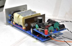
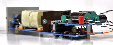
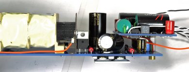
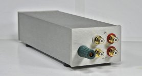
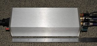
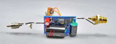
In my recent build, I tried to reduce the length of the chassis to match pre-cut tubing I'm using for DACs. Normally, phono stage requires at least 9.5" enclosure length. By placing amp board over the power supply I was able to reduce the required length to 8" only.
To prevent possible transformer influence, I used mu-metal shielding.
To prevent possible transformer influence, I used mu-metal shielding.
Attachments
Banned
Joined 2002
Looks really good Peter,
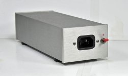
One question, how come you have the power at one end and rca's at the other ? Wouldn't it look better if it was all on one side and a nice little Green power led on the front ? I know your trying to isolate the ac from dc and noise and interference right ? However isn't that all removed from the equation because it's in a metal enclosure ? have you tried putting the transformer/psu in another box with a umbilical cord ?
Just some thoughts and questions i had")
Looks nice and sexy tho, always admired your machine work.
J'
One question, how come you have the power at one end and rca's at the other ? Wouldn't it look better if it was all on one side and a nice little Green power led on the front ? I know your trying to isolate the ac from dc and noise and interference right ? However isn't that all removed from the equation because it's in a metal enclosure ? have you tried putting the transformer/psu in another box with a umbilical cord ?
Just some thoughts and questions i had
Looks nice and sexy tho, always admired your machine work.
J'
Use LED as volt ref
Have you tried LED reference (normal one, not low current) instead of D11/D12?
I am using audio-gd shunt reg with VSPS.
Have you tried LED reference (normal one, not low current) instead of D11/D12?
I am using audio-gd shunt reg with VSPS.
I had a chance today to do some careful comparisons with PS and as suggested earlier, I did remove C3/C4 across current source: the sound become noticeably better without those caps (less coloration). I also removed C5/C6 and further improvement was observed. I tried without C9/C10 as well, but circuit actually sounded better with those caps in place. Nichicon FG was preferred here over BG STD, something I suspected already. BG N 10-47uF could be another good choice, although not that much better than FG.
I also did some testing with constant current regulator types. I really liked the old production ON Semi, National was second, then the new production ON Semi while Linear Technology LT317 was the worst; nice sound but too technical, ON Semi was OTOH much more musical.
Attached is updated PS schematic.
Attachments
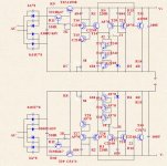
Looks nice but C3, C4 in the shunt regulatorCan you explain this?
Peter, the electro cap across the current source R is the LM317 CCS is completely wrong, as it stops it from being a CCS at anything other than DC.
The explanation came up quite by surprise. I was building some new circuits this week and couldn't figure out why I can't get proper voltage output on negative side.
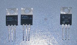
When I was using Variac, bringing voltage slowly up, it worked fine for a proper -15V rail. However, when using power switch (voltage instantly on), the output stayed at 4.3V. Initially, I was quite stuck, as everything seemed to be fine, then I decided to check for a cap across current source (LM337) and that brought some results:
I tried 3 different brands of LM337 and two on a left do not work without C4/100uF across them (voltage stays at low level). The Motorola works fine without caps.
Now, can someone explane that?

Attachments
peter:
i cannot explain the particular symptom you see, but several years ago, i ran into a problem with some lm337 parts that were also provided by the mfr on the left. it turns out there was a bad batch that preferred to oscillate instead of regulate properly, no matter what capacitance one applied (or did not apply) at the output. i decided to either change my circuits to only use lm317 when i could and use linear technology for negative regulators when i couldn't.
mlloyd1
Same issue with negative supply
Peter-
I have exactly the same issue: without C4, the negative regulator voltage is very low - mine is around 2.7VDC, unless I bring it up slowly on a variac, when it works fine at -15VDC. I did notice that the regulators seem to drop out of regulation very easily - in my case if the AC supply drops below 115V, the supplies (both plus and minus) begin dropping below 15V. Could this be related? Might it make sense to set the regulator to +/-12 or 13V to give them some headroom in case of line fluctuations?
Mike
The mains at my house are 123V, so I never experienced out of regulation issues.
I actually started with LM317 for both positive and negative sections, but noticed that it's very tricky to get proper voltage drops on standardized resistor values; things got easily off with only slightly varying secondaries voltage, which depended not only on transformer types but also on actual mains levels.
That's why I switched to LM337 in negative section and things started to work "normal". The recent capacitors omission brought things out of balance again, but the solution is to either use specific regulator brand (Motorola seem to work fine) or simply leave C4 in place.
You can easily lower regulated voltage level by changing R7/R8 to a suitable values. With Hammond 229D24 and 12R resistors I'm aiming at 100mA current and reasonable heat dissipation on heatsinks. If your secondary voltage is too low, lower the output DC to get enough regulation margin.
And now for something slightly different.
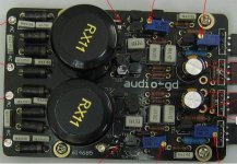
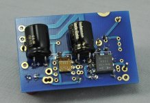
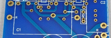
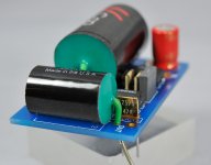
For some special applications, the amp board can be cut in half and there are additional pads for separate pairs of caps per channel, closer to the chips.
I also now remember why one set of jumpers is in bottom layer and the other in top layer: for regular application, when board is not divided, only top layer jumpers should be installed. The bottom jumpers are only for those "special" caps, connecting their pins to ground. The wires from PS should be connected directly to the caps, although additional ground pad is also provided (the + sign on one of the caps is misplaced, negative pins should be on the inside in both channels).
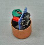
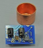
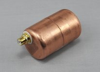
The advantage of such arrangement is that the complete one channel section fits inside 1 1/4 copper cap or coupling, which with some imagination allows to mount such assembly directly on the interconnect. I will post some examples later
For some special applications, the amp board can be cut in half and there are additional pads for separate pairs of caps per channel, closer to the chips.
I also now remember why one set of jumpers is in bottom layer and the other in top layer: for regular application, when board is not divided, only top layer jumpers should be installed. The bottom jumpers are only for those "special" caps, connecting their pins to ground. The wires from PS should be connected directly to the caps, although additional ground pad is also provided (the + sign on one of the caps is misplaced, negative pins should be on the inside in both channels).
The advantage of such arrangement is that the complete one channel section fits inside 1 1/4 copper cap or coupling, which with some imagination allows to mount such assembly directly on the interconnect. I will post some examples later
Attachments
Last edited:
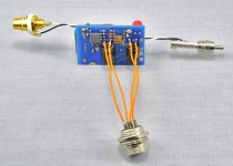
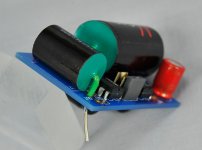
This is how it's wired for testing, before going into permanent enclosure (made out of 2 copper caps)
Ground wires from input and output connect to SG pads. Two separate grounds from PS connect directly to bypass caps. The enclosure is connected to ground from turntable (it is not connected to SG)
Ground wires from input and output connect to SG pads. Two separate grounds from PS connect directly to bypass caps. The enclosure is connected to ground from turntable (it is not connected to SG)
Attachments
I did some more tests recently. There is always a question about capacitor orientation with regards to outer foil. Normally, OF is placed towards the output, however with caps in feedback position I wasn't quite sure which way it would be better.This is what manufacturer says:
Although the V-Caps are not polarized, many have found it is best to keep the lead orientation relative to the innermost and outermost foil consistent. The green lead (short lead on OIMP series) indicates the outermost foil, and should always be connected to the lowest impedance return path to ground in the circuit. In practice, this means the outer foil should be connected towards the plate of first stage, when used in amplifiers. If using as a bypass cap to ground, connect outer foil to ground. If using as a bypass cap from a signal to B+, connect outer foil to B+. Another way to identify is the “V” in the V-Cap label indicates “inner foil” side of the cap
The recent experiments confirm my initial speculations: for feedback caps it still applies the same as for coupling applications, so the outer foil should be towards the output. On my boards, the orientation for V-Caps is marked with R, which indicates red lead. Placing the caps in reverse, will create more diffused sound and inferior bass definition.
Another thing I always wanted to check, was how the 47R output resistor affects sound. I used nude Vishay here (R7 on schematic). With the resistor, the midrange spectrum is more pronounced, but the soundstage is not as big; it also affects immediacy and bass definition, so we decided not to use that resistor. You can either place a jumper in its place or take the output directly from cap's lead.
Attachments
Last edited:
- Home
- More Vendors...
- Audio Sector
- The Phono Stage