This my first post so please forgive me if this is wrong place to ask this question.
I recently put together one of the LM4780 boards from Audiosector (to use in stereo for testing before finishing the whole kit).
I have tried three different potentiometers but there seems to be very little attenuation and certainly not all the way down to cut off.
The first two, a 10k and 20k (with a "B" designation I assume for "Linear") the attenuation is faint at best and not down to silence.
The third pot, is one retrieved from my old Technics amp with the makings of 100k Ohm B. This one does noticeably attenuate but not to cut off. To help make it clear what I am saying, the volume goes from loud to less loud.
Power is from 18v +- rails and rectifiers to 26.5v and 25v.
Thank you for any assistance on this question.
Phil
My latest gainclone
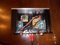
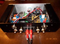
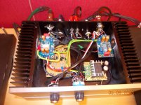
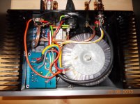
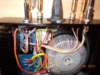
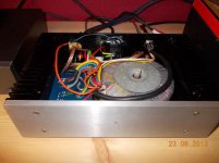
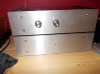
I thought someone may be interested in my latest, and last gainclone. It is rather unusual as to keep all the ac away from the inputs and still have an isolated speaker protection system, I have mounted the speaker protection board in the psu box, therefore the speaker sockets are on the psu box. This also gave me room in the amp box to fit a phono board for my vinyl.
I thought someone may be interested in my latest, and last gainclone. It is rather unusual as to keep all the ac away from the inputs and still have an isolated speaker protection system, I have mounted the speaker protection board in the psu box, therefore the speaker sockets are on the psu box. This also gave me room in the amp box to fit a phono board for my vinyl.
Attachments
Need some help with audiosector kit
I just put together an my Audiosector LM3875 kit with a PSU I had built from Chipamp.com. I used a 24 volt transformer, and have 33.6 v in both rails. I used a 10 uf electrolytic cap in place of r1 for DC coupling. I used a 20k potentiometer that I had in my last Chip amp that I busted up to build this.
So in 1 channel I'm getting about 66 mV of DC offset, and in the other about 115 mV. There is no difference when I move the volume pot from full off to full on.
I noticed a couple of little breaks in one of the 1500 uF caps, like maybe I brushed my soldering iron against it a couple of times, on the side with the lower DC offset.
I'm not sure how to troubleshoot. I'm thinking the potentiometer isn't working since it doesn't change the offset, so maybe I should bypass it and see what I get.
Any suggestions?
Another question I have is whether it is OK to install an LED between V+ and PG+ coming off of the power supply.
Thanks in advance for any help.
I can't see any problem installing a led. Some people fit one for pos and one for neg rails. The difference in offset is quite large. You could try replacing R1 and see what the difference is. The tranny and voltage are good. 20k pot should be LOG. Not sure what you mean by no difference in the pot. Is the volume changing. If not I would check the wiring and earthing on both channels.
Thank you.
In Peter's instructions he says that the offset should change when the volume is increased or decreased, and mine does not. I haven't hooked it up to speakers yet, so I'm not sure if the volume changes. I don't have R1 installed, and instead have a 10 uF electrolytic capacitor installed for DC blocking. Maybe I should install R1 instead.
Josh
Hi All.
I pulled out the little caps from the R1 positions and installed the resistors. My volume pot is working ok. With nothing connected to the amp, on one side I get 10 mV to 37 mV offset depending on the volume, and on the other side I get 46 mV to 86 mV offset depending on the volume. Does this indicate a problem? Is the side with the higher offset destined to sound worse? I listened to it briefly in the middle of the night here at low volume, so I know there is sound, but I haven't been able to judge it too much yet. If the channel with the higher offset is a problem, can anyone suggest any trouble shooting steps to take?
On a separate note, I am using an Alpha 20K dual Audio pot, which I think cost about $3. I am thinking about getting an Alps Blue Velvet from PartsConnexion. Anyone have anything to say about how much of a difference that might make and what that difference would be?
Thanks for any responses!
The offset sounds OK although 86mv could be considered high. I have tried lots of pots and to be honest find it difficult to hear any differences. Others will disagree. The only faulty component I have found with irregular offset is the IC itself. You could check that the resistors around the input are grounded properly (soldered).
Thiose offsets are perfectly fine and they mostly depend on the chips: http://www.diyaudio.com/forums/audi...-kit-building-instructions-5.html#post1524877
A little help needed please. Completed my 2nd LM4780 amp board, but it runs hotter than the first which only gets warm after 30 mins or so of use. Both amps are in individual heatsink cases (8"x2") boxes. With input loaded with 2k resistor or fed by Mezmerize, the supply quiescent current is about 165mA, rail voltages +/- 26 volts, output load nom 8ohm speaker. Sound is not distorted. Tried adding 10Uf and 0.1uF caps across each rail in addition to normal 1500uF caps,also 100pF between pins 15/16 & 21/22, but no change. Any suggestions or is it just a chip that wants to run at high quiescent current?
Last edited:
DC Offset high?
Havent looked at pin out so maybe 100pf is across feedback resistor. Maybe try a .1uf just to test and see for sure if its oscillations or not.
Forgot to mention the offset, 4-11mA depending on input. Pins 15,16,21,22 are signal inputs, I'll give the 0.1uF caps a try.
BTW my Lighter Note is working a treat, amazing transparency!
Best
Ian
Offset is measured in Volts at the output of the amp. It will hopefully measure in low millivolts mV.
For oscillations the capacitor would go from output to inverting input allowing all high frequency oscillations to make their way back to the inverting input so that they may be removed. If its oscillating then the high frequency oscillation will see the capacitor as a short to the inverting input. The inverting input will flip that oscillation upside down or in other words make a negative copy of it so that when the output is added to the negative copy you have zero. If oscillation is your problem then this will do the trick or at least point to the problem.
DC offset - just put your DMM on Volts and measure the output on the speaker terminals on your amp. I do this with a speaker attached and music playing but you might have a lot of offset so detach your speaker and check and if its low then attach and check again.
Here is a thread on testing for DC offset. One of their explanations may pertain more to your amplifier than to mine
http://www.diyaudio.com/forums/solid-state/152919-test-dc-offset.html
http://www.diyaudio.com/forums/solid-state/152919-test-dc-offset.html
Here is a thread on testing for DC offset. One of their explanations may pertain more to your amplifier than to mine
http://www.diyaudio.com/forums/solid-state/152919-test-dc-offset.html
The offset I quote is at the output, it varies depending on whether the input is shorted, open circuit or "loaded" with 2kohms. Tried 0.1uF caps across the inputs (no change) and across feedback resistors (motorboating). The amp is configured in parallel mode. Disconnecting the output paralleling resistors lowered the quiescent to 100mA, which is near the quoted spec of 110mA. Measuring the voltage at the inverting inputs revealed one input at -0.1V and the other at -1.2mV, so there is an imbalance in the feedback resistors. Probably means that the amps are fighting each other, new 0.1% resistors on order!
Many Thanks for your help.
Last edited:
- Home
- More Vendors...
- Audio Sector
- Commercial Gainclone kit- building instructions