Ah...then I have a completely different idea...are your chips the insulated type or naked? National make both. If naked it is possible that you need to insulate them.
Its the LM 3875 TF all black and i think its insulated type.
since its Sunday i cannot get caps as peter suggested but i tried to turn off all apliances that might produced interference. Wifi, wilress phones etc.
Nothing changed.
i connected a source and when the music started this loud audible mors code stoped. The music was more cleared when i turned the pot to louder. There were some static in the music thous but the noise did not exist. It appeared again in the time between the songs or when a song had a pause.
I have also connected a filer in the input of the psu to be on the safe side.
Any ideas?
Last edited:
Ok that was it !!!
its idiotic !! I should have notice that earlier. The speaker had burned its crossover and thus produced this sound !!!! it was a small wooden 2 way jcv 6ohm 40w speaker that could not handle the power. I tried it with a bookself 80w 8 ohms crystal audio and voila!!!
Though some clipping occurs but i think with bigger speaker i will not have any problems.
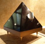
soon some finished pics !!
thank you
Nick
its idiotic !! I should have notice that earlier. The speaker had burned its crossover and thus produced this sound !!!! it was a small wooden 2 way jcv 6ohm 40w speaker that could not handle the power. I tried it with a bookself 80w 8 ohms crystal audio and voila!!!
Though some clipping occurs but i think with bigger speaker i will not have any problems.
soon some finished pics !!
thank you
Nick
could the damaged speaker have been overloading the chipamp and the protection systems were intermittantly switching the chipamp to some safe mode?
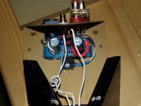
How is the TF chip mounted to the heatsink?
Where does that cable go?
Is the TF thermally coupled to the heatsink or is it mounted dry?
How does the heat get out of the TF?
How is the TF chip mounted to the heatsink?
Where does that cable go?
Is the TF thermally coupled to the heatsink or is it mounted dry?
How does the heat get out of the TF?
could the damaged speaker have been overloading the chipamp and the protection systems were intermittantly switching the chipamp to some safe mode?
Perhaps i dont really know !
It is mounted through a bolt. Actually the bottom of the amp is the heatsink (2cm thick aluminum plate).How is the TF chip mounted to the heatsink?
its going to the chassis ground on the amp boardWhere does that cable go?
I use Zalman thermal greace used for computer chips.Is the TF thermally coupled to the heatsink or is it mounted dry?
the Aluminum board stays pretty cool if thats what you mean. The tf is attached to the heatsink throug a copper leaf.How does the heat get out of the TF?
Nick
your answers do not look like the pic (superb quality and focus).
Sorry i lost you
") Why my answers does not look like the pic? in which case?
Why my answers does not look like the pic? in which case?thank you
Nick
what is between the chassis base plate and the TF mounting face?
What you listed is not what I can see in the pic.
i see , well there is a small copper leaf and some thermal paste, the nfoto is actually reaaly big if you enlarge it you can see them
Thnax for your remarks.
Nick
remove all that rubbish from between the TF and the heatsink.
If the TF is too far off the heatsink to bolt on direct then insert a solid block of aluminium to fill the gap.
The surfaces of the block must be flat and fairly smooth.
The interface between the TF and the Block must be filled with thermal compound as thin as possible with no air and the interface between the block and the heatsink must alsp be filled with a thin layer of thermal compound.
Nothing else should be in there to interfere with the heat conduction from TF to heatsink.
The TF is very poor at conducting heat to the sink, do not make it any worse.
Next time insert the 3886 from the back (bending the legs in the opposite direction) to allow direct mounting to the heatsink.
Last edited:
Andrew is right. That spade appears to be under the chip, between chip and heatsink. The chip must be intimately attached to the heatsink.
Also, please use your DMM and measure for DC voltage on your amp outputs that go to your speakers while the thing is playing.
I am worried you burnt your voice coil by inserting DC from the amp into the speaker. It slowly cooks the coil and the speaker will still play while this is happening.
Still, the way that thing is connected to the heatsink just looks wrong. Nothing should connect to that chip besides the board and the sink. Thermal paste only between the two. If you want to ground the sink do that somewhere else, not near the chip or any part of the board that has bare wire/leads.
Uriah
Originally i thought copper sheet between because it will take the heat faster and give it to the aluminum for spreading.
It will act as spreader only if it's larger than the chip. In your assembly it's not, and it actually makes the heat transfer harder. And inserting the spade inbetween is completely wrong.
Read about measuring DC offset here: http://www.diyaudio.com/forums/audi...-kit-building-instructions-5.html#post1521304
Thanx Peter
Yes i got it about the spade, i should have thought of it.
The offset is right thought, 32mv with pot to min, and 71 with pot to max.
Nick
this indicates that the inputs of the chipamp are not DC blocked from the volume pot.The offset is...... 32mv with pot to min, and 71 with pot to max.
this indicates that the inputs of the chipamp are not DC blocked from the volume pot.
Ok, is there something i should do about it?
According to the reading the Peter suggested, the numebers look logical.
Aren't they?
Nick
- Home
- More Vendors...
- Audio Sector
- Commercial Gainclone kit- building instructions