roger_lew said:and I figure my rail voltages will be about 50V (35 x 1.4).
Those would be way too high, you shouldn't be exceeding 40V on rails.
Check this thread for regulated supply option: http://www.diyaudio.com/forums/showthread.php?s=&threadid=56106&highlight=
However, don't take seriously the hype that it elevates the chipamp to a league of it's own.")
However, don't take seriously the hype that it elevates the chipamp to a league of it's own.
Thanks again Peter. That thread was helpful (despite the hype ).
I suppose the easiest way to go about this is to give up on dual mono and have a single PSU power both channels. That way I can use each transformer to power each rail of a regulated power supply (with center tap wave rectifier).
Building a dedicated regulated supply for each channel isn't straight forward enough for me to attempt given my very limited experience. Since I have center tapped transformers building one seems to require a 5 amp negative voltage regulator (complementary ICs to the LM338) which don't seem to be commonly available.
Does this plan seem reasonable?
Roger
). I suppose the easiest way to go about this is to give up on dual mono and have a single PSU power both channels. That way I can use each transformer to power each rail of a regulated power supply (with center tap wave rectifier).
Building a dedicated regulated supply for each channel isn't straight forward enough for me to attempt given my very limited experience. Since I have center tapped transformers building one seems to require a 5 amp negative voltage regulator (complementary ICs to the LM338) which don't seem to be commonly available.
Does this plan seem reasonable?
Roger
roger_lew said:... one seems to require a 5 amp negative voltage regulator (complementary ICs to the LM338) which don't seem to be commonly available.
You don't need that, both positive and negative rails are powered from a (positive) LM388 regulator: http://www.diyaudio.com/forums/attachment.php?s=&postid=627945&stamp=1114473823
Right, we are on the same page. If I build a single power supply for both channels I don' t need a negative voltage regulator. I can use two LM338s.
But if I wanted to go full mono and build a regulated dual channel supply with a single center tapped transformer I would need a high current negative voltage regulator.
http://www.diyaudio.com/forums/showthread.php?postid=1616994#post1616994
http://www.diyaudio.com/forums/showthread.php?postid=1617073#post1617073
If you use half of each transformer, you can build a positive regulator on each.
Couple the two +ve supplies together to create a dual polarity supply.
What a waste of resources.
If these transformers are so important to you then buy amplifiers that suit +-50Vdc supplies.
Couple the two +ve supplies together to create a dual polarity supply.
What a waste of resources.
If these transformers are so important to you then buy amplifiers that suit +-50Vdc supplies.
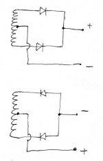
You can use one (complete) transformer per rail, if you wire them as in attached schematic. This setup will also allow positive regulator in a negative rail.
Such supply would be powering both channels.
If you need dual mono configuration, with separate supply for each channel, you need to source suitable negative regulators.
Such supply would be powering both channels.
If you need dual mono configuration, with separate supply for each channel, you need to source suitable negative regulators.
Attachments
Andrew,
Thanks for the advice. I'm dead set on building a gainclone from a audiosector kit due to their simplicity and the detail Peter has put into the instructions. Whether I use these transformers with a regulated PS or buy toroids is still something I'm tolling over. I might just save these for a more suitable project down the road.
Peter,
I placed an order for a premium kit. Thanks for the schematic. We are still on the same page.
Hi Peter!
I just finished my recent project, a gainclone with integrated usb dac and volume control. It almost works perfectly from the first minute on, but there is one strange thing: There is a little bit of audible hum (with ears right beside the speakers), but ONLY when the volume pot is completely turned down OR completely turned up to the max. Between min and max everything is fine.
Any ideas?
I will try to post some pics of the setup in the photo gallery thread in the next days...
ps: grounding is done very carefully with both amp boards connected together at chassis ground pins with a massive 1,5mm copper wire (solid), and from the middle of this connection goes a wire to the chassis ground point, where earth is connected. I didn't use the 10ohm resistor that you normally use, because you said somewhere it isn't really neccessary.
Regards - martin
Premium Kit Arrived
Hello Peter,
Just received your Premium Kit...Outstanding Quality! Thanks.
I'm beginning the process of gathering components from various sources, and would appreciate your opinion as to whether a dual-mono configuration(2 trafo's & 2 rectifier boards)is sonically superior to the stereo configuration. Both would be housed in the same chassis, and would use a Noble 50K stereo pot for volume control. Should I go the extra mile, and build Monoblok's each with Noble 50K mono pots? I will be using only digital source.
I plan on building a pair of metronome ML-QQWT's using the Fostex FE127e 8ohm drivers for this setup.
I have read and re-read this thread countless times, and frankly, I'm overwhelmed with the options and excellent information provided by yourself, and others. This newbie would appreciate your thoughts and comments.
Thank you,
Thomas
The advantage of dual supply was mentioned here: http://www.diyaudio.com/forums/showthread.php?postid=1517735#post1517735
If I want to make my best effort, I go with dual mono: in reality, I've heard stereo amps sounding better than monoblocks so there is more to it than just two transformers Just go with what's most convenient.
The two boards should be connected at OG pads (output ground). To the middle of that connection should be connected grounds (PG+ and PG-) from rectifiers. Chassis connects here as well, you may use 10R resistor, but not neccessarily.
Did you use 220R input series ressitors?
If I want to make my best effort, I go with dual mono: in reality, I've heard stereo amps sounding better than monoblocks so there is more to it than just two transformers
Just go with what's most convenient.martinbls said:Hi Peter!
I just finished my recent project, a gainclone with integrated usb dac and volume control. It almost works perfectly from the first minute on, but there is one strange thing: There is a little bit of audible hum (with ears right beside the speakers), but ONLY when the volume pot is completely turned down OR completely turned up to the max. Between min and max everything is fine.
Any ideas?
I will try to post some pics of the setup in the photo gallery thread in the next days...
ps: grounding is done very carefully with both amp boards connected together at chassis ground pins with a massive 1,5mm copper wire (solid), and from the middle of this connection goes a wire to the chassis ground point, where earth is connected. I didn't use the 10ohm resistor that you normally use, because you said somewhere it isn't really neccessary.
The two boards should be connected at OG pads (output ground). To the middle of that connection should be connected grounds (PG+ and PG-) from rectifiers. Chassis connects here as well, you may use 10R resistor, but not neccessarily.
Did you use 220R input series ressitors?
Hi Peter!
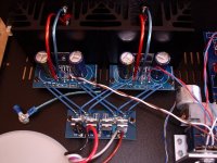
Here is a pic how I connected it. I always thought that chg means "chassis ground"... Am I wrong here? But I thought this kind of grounding might be the most simple way.
The solid copper wire from chg to chg is underneath the amp boards, and in the middle a stranded wire is connected which goes to the chassis ground (earth) point. For the bolt I screwd a threaded hole into the chassis bottom plate for proper contact.
And yes, because of what I read about the possibility of oscillation and things like that, I decided to use the 220R input resistor.
And to say this once again: It only hums a bit when volume pot is completely at min or max. A little bit more than min or a little bit less than max, there is no hum at all. So I think in the end this shouldn't bother me too much because I never tend to listen at max volume or min volume position ;-)
martin
Attachments
Thank You Peter,
I do want to make this my best effort, as this is my first retirement project.
I decided not to use the 220R input series resistors, as you had suggested early in this thread. Curious as to why almost all the "classic" LM3875 schematics show them. I trust your experience with this circuit more than schematics though.
You anticipated my next question regarding grounding. In effect, I will be using the picture in post #77 as a guide. I have seen some people using a very heavy guage ground bus, but is 14Ga solid copper adequate? I was going to use the 10R resistor at the chassis ground lug, or would it be better at the IEC ground terminal?
I will be ordering two transformers now. I was going to order the Avel Y236750 330VA 25V+25V toroids, but could save about $40.00 if I order the Y236652 250VA 25V+25V version and put that money to good use in the chassis. Am I being pennywise, and pound foolish?
Your patience must be tested daily by these endless newbie questions!
Thanks,
Thomas
The two boards should be connected at OG pads (output ground). To the middle of that connection should be connected grounds (PG+ and PG-) from rectifiers. Chassis connects here as well, you may use 10R resistor, but not neccessarily.
I connected chg (which I assumed was chassis ground) to my star ground and ran the OG to my output jack on the outside ring. I have theses insulated from the chassis.
http://picasaweb.google.com/tom.bro...gCPaAyKmCqN6wdQ#slideshow/5331279046144343858
Is this where I went wrong?
Tom
martinbls said:Hi Peter!
Here is a pic how I connected it. I always thought that chg means "chassis ground"... Am I wrong here? But I thought this kind of grounding might be the most simple way.
The solid copper wire from chg to chg is underneath the amp boards, and in the middle a stranded wire is connected which goes to the chassis ground (earth) point. For the bolt I screwd a threaded hole into the chassis bottom plate for proper contact.
And yes, because of what I read about the possibility of oscillation and things like that, I decided to use the 220R input resistor.
And to say this once again: It only hums a bit when volume pot is completely at min or max. A little bit more than min or a little bit less than max, there is no hum at all. So I think in the end this shouldn't bother me too much because I never tend to listen at max volume or min volume position ;-)
martin
Yes, CHG means chassis ground, and it's the optional hook up point for ground connection mainly when using amp in monoblock configuration.
Your wiring is OK and in most cases it worked fine, but some people also complained on low level hum and I guess that could depend on system configuration and source's type. To clear up those type of problems, I came up with a new wiring scheme (for stereo amps), and it's explained here: http://www.diyaudio.com/forums/showthread.php?postid=1518369#post1518369
boltzmann said:I decided not to use the 220R input series resistors, as you had suggested early in this thread. Curious as to why almost all the "classic" LM3875 schematics show them. I trust your experience with this circuit more than schematics though.
You anticipated my next question regarding grounding. In effect, I will be using the picture in post #77 as a guide. I have seen some people using a very heavy guage ground bus, but is 14Ga solid copper adequate? I was going to use the 10R resistor at the chassis ground lug, or would it be better at the IEC ground terminal?
I will be ordering two transformers now. I was going to order the Avel Y236750 330VA 25V+25V toroids, but could save about $40.00 if I order the Y236652 250VA 25V+25V version and put that money to good use in the chassis. Am I being pennywise, and pound foolish?
It is a common practice to use series resistor with amp input: it separates the input from outside world and prevents interferences, but my experience with those amps shows that the amp can work without it quite well and actually sounds better.
Post #77 shows proper wiring for stereo amp. In case you are using dual mono configuration (2 separate and not shared supplies) it does not apply. In that case you would be wiring the amps as pictured here: http://www.diyaudio.com/forums/showthread.php?postid=1518369#post1518369 and using CHG pads for chassis ground connection (install 10R to break any ground loops). IEC ground terminal connects directly to the chassis at the same point.
14ga wire is fine here.
If it's your best effort, I wouldn't be trying to save $40 on transformers
tbrooke said:
I connected chg (which I assumed was chassis ground) to my star ground and ran the OG to my output jack on the outside ring. I have theses insulated from the chassis.
http://picasaweb.google.com/tom.bro...gCPaAyKmCqN6wdQ#slideshow/5331279046144343858
Is this where I went wrong?
Nothing wrong with that, the amp will work fine.
I only recommend different ground arrangements if someone has low hum problems.
- Home
- More Vendors...
- Audio Sector
- Commercial Gainclone kit- building instructions