I finished putting it all together last night and measured the DC offset. I've got a 47K Pot installed and with the volume all the way up I get -42mv and -34mv across the channels, and with the volume all the way down I get about -2.4mv and -1.9mv.
Looking at the post with the range of offsets for the batch of 40 chips then I think my measurements are within sensible offset ranges, but I just want to double check that you guys don't think my measurements are anything to be concerned about.
Thanks
Looking at the post with the range of offsets for the batch of 40 chips then I think my measurements are within sensible offset ranges, but I just want to double check that you guys don't think my measurements are anything to be concerned about.
Thanks
westers151, your readings are perfectly fine
Well, that's very easy to correct and I already mentioned it earlier. Just install a coupling cap in place of R1: 4.7 - 10uF is fine. This is how Gaincard is built and last time I was checking this amp, the offset was steady at 80mV and not dependant on volume setting.
The early versions of my commercial amp (AMP-1) had the input caps installed. Based on customers feedback though, we decided not to install those caps any longer.
AndrewT said:I would never use a topology that allows the DC offset to vary over 30 to 40mV due to changing the position/setting of the volume control.
Well, that's very easy to correct and I already mentioned it earlier. Just install a coupling cap in place of R1: 4.7 - 10uF is fine. This is how Gaincard is built and last time I was checking this amp, the offset was steady at 80mV and not dependant on volume setting.
The early versions of my commercial amp (AMP-1) had the input caps installed. Based on customers feedback though, we decided not to install those caps any longer.
I have a problem - no sound, and I can't figure out what is wrong. I've double checked the pot wiring and it is as per the description posted earlier. I've paid particular attention to the input and output wires and these are wired correctly; 3 pins on each of the dual gang - middle pin I've wired to the IN terminal on PCB, and the RCA output is wired to Pin 1 on the Pot (pin 1 is far left, with the pins facing upwards). Pin 3 I've wired to SG on the PCB and is my earth.
Earth wire from the RCA's is also to SG on the PCB.
Speaker terminals are wired with one of the outputs connected to the OUT terminal on PCB and the other connected to the OG terminal on PCB.
I figure it doesn't matter which of the speaker terminals are connected to OUT or OG, just as long as both channels are consistent. On each channel I've taken the Red speaker terminal to the OUT terminal on PCB, and the Black terminal to OG.
Star ground is also connected to the OG terminal on each PCB.
Fuse hasn't blown (it's now a 4 amp fuse).
I've connected my Sony Walkman MP3 player to the circuit - battery is fully charged, and MP3 volume is up around 3/4 full. Still no sound throughout the whole of the pot's arc (i.e from low to high sound).
Everything is on a block of MDF, with the spaker terminals mounted on some metal brackets, but the actual terminals are insulated from the brackets by plastic insulators. See here for the actual terminals.
So I'm stumped.
Oh, Pot is a 47K log dual gang item.
westers,
Is the reason you do not post photos that you cannot take any or that you are having problems with the size of the jpegs, if the latter is the case then this can be sorted.
If you have any but cannot post them then please email me with the images and I will do something with them.
Sorry to harp on about this but it would help you a lot!
Alan
 )
)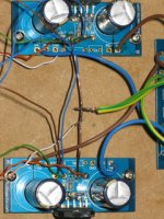
And another - Thin green wire is the earth from the RCA to SG, thin blue wire is the earth from the pot to SG (same on both circuit boards).
Thin brown wire is the output from the pot to the IN on the PCB.
The other thin wire (which is a browny/orange) is the red speaker terminal going to the OUT pcb.
The white wire (with a slight thin brown stripe) is the black speaker terminal connected to the star ground.
Star ground is the copper wire connected to OG.
Attachments
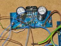
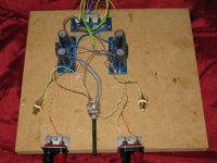

westers - I cannot see enough wires going into the psu board from the transformer - and one of them looks like an earth.
I normally connect the PG+ and PG- from the psu direct to the same on the amp boards - but I do not think that would stop it working.
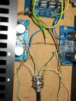
Also not sure about the pot - it looks OK - but a close-up please.
I normally connect the PG+ and PG- from the psu direct to the same on the amp boards - but I do not think that would stop it working.
Also not sure about the pot - it looks OK - but a close-up please.
- Home
- More Vendors...
- Audio Sector
- Commercial Gainclone kit- building instructions