Do you have any photos of the mains/transformer/bridge connections and do you have details for the transformer. What transformer is it you are using?westers151 said:However, looking at the connections (both primary and secondary to the Bridge) they're all connected up correctly and nothing is shorting out.
I ask because it sounds more and more like a wiring problem, although having said that I own an OTL valve amp which you do not switch on using its switch (this stays permanently on - the wall socket is used as the on/off) otherwise it blows it fuses because of the spike across the switch.

I do not know about the others but would using a larger fuse (for the moment) allow voltages etc to be checked
 or would that cause more damage?
Did you try switching on when only the transformer / bridge / caps are connected - i.e. remove the link to the amplifier board.
Does the problem persist?
As Andrew said - TAKE CARE

Best of luck
Alan
No pictures, plus I've unsoldered the connections now in prepartion for crimping connectors and connecting it as per Nuuk/Andrew suggest. Should have done that before, but you learn from your mistakes.
I've checked the connections multiple times and over several days, especially when I'm fresh and alert. Blue from the primary was to the neutral IEC switch connection, and brown was to the live.
I only had the bridge connected to the transformer - I did take notice of Peter's comments about not connecting the amp until you know the power supply is working, and now I know why
I could use a larger fuse, but I think that's curing the sympton rather than the cause. For initial testing the lightbulb should allow me to make sure wiring is connected properly and secondary voltage is correct. Assuming that is the case then I'll have to build a soft start circuit to go in front of the primary connection. It's not something I know what to do, although I've google it and come up with some simple power resistor/relay solutions, although I'm not 100% sure how to wire that.
You can measure the mains voltage at your distribution board or at a socket outlet.
No pets around, no kids around.
No distractions from her indoors!
Set your DMM to 600Vac.
If at a socket outlet, open the protection shutters by inserting a non conductive probe into the Earth receptacle.
VERY CAREFULLY
Insert one DMM probe into Neutral (the one on the left).
Insert the other DMM probe into Live (on the right).
Your DMM is now at mains voltage.
Your meter will read between 226Vac and 254Vac.
Repeat this at various times to see if a particular time when you have lights on is much higher voltage than other times of the day/night.
If all your readings are over 240Vac, ask someone to check your DMM.
If all your readings are significantly over the nominal 240Vac, you can ask the Supply Company to check their voltage and if necessary adjust it.
There are tappings on the local transformer to allow this adjustment.
Hello all! i've taken the bait - a tiny bundle with the LM4780 dual mono kit arrived today - thanks for quick delivery, Peter
first question... i plan to use it with both 'normal' 8 ohm speakers and a pair of jordan jx92s MLTLs, but mainly the jordans. As the jordans are 6 ohms does this rule out the bridged version of peter's kit? Should i build the parallel config and expect to see the power advantage only with the jordans, not the 8 ohm speakers?
thanks
ben
Ok, some success, but also some puzzlement.
Firstly it's the inrush that is causing the fuse to blow. I did what Peter said and it blew the fuse. However I then built the light bulb tester and no more blown fuses.
I measured the Secondaries when they weren't connected to the bridge and they both read 27V, 2V over what they are supposed to be (25V), but I put that down to the mains voltage not being exactly 230V (I checked it today and it was 237V).
I then connected hte secondaries to the bridge and measured that voltage (still with the light bulb tester in place and I got - 24V and +24V. Not what I was expecting.
Anyone care to offer an explanation?
What is clear is that I need a soft start mechanism. I've found a simple resistor/relay circuit here . Is it any good, or would you recommend something else?
thanks
presterjohn said:As the jordans are 6 ohms does this rule out the bridged version of peter's kit? Should i build the parallel config and expect to see the power advantage only with the jordans, not the 8 ohm speakers?
It shouldn't be a problem to use bridged LM4780 with 6 ohm loads, of course the results will depend how loud you like to play, what type of music and on heat dissipation capabilities of your assembly. I've been using bridged LM3875 for almost a year with 4 ohm speakers (FAL) without major problems.
Please note that in order to use the amp in bridged mode you need to supply balanced signal to the amp, as the amp by itself will not do conversion from unbalanced source.
westers151 said:measured the Secondaries when they weren't connected to the bridge and they both read 27V, 2V over what they are supposed to be (25V), but I put that down to the mains voltage not being exactly 230V (I checked it today and it was 237V).
I then connected hte secondaries to the bridge and measured that voltage (still with the light bulb tester in place and I got - 24V and +24V. Not what I was expecting.
Anyone care to offer an explanation?
The rating of a transformer is with a full load applied, when idle, the voltage will be higher by a regulation margin.
When you connect secondaries to a bridge, you will see rippled DC and you need to add smoothing caps to see actual DC voltage (in that case it should be approx 1.4 x AC volts). That will happen when amp boards are connected, as the caps are there.
Thanks Peter - I was just re-reading your testing methodology and just saw your secondary measurements were 10V lower without anything attached to them.
Mine are also roughly 10V less than I expect - not sure if that's coincidence or not.
Anyway, I now feel happy about attaching the chip amp to the bridge, but first I need to build a soft start mechanism to stop the fuses blowing.
Mine are also roughly 10V less than I expect - not sure if that's coincidence or not.
Anyway, I now feel happy about attaching the chip amp to the bridge, but first I need to build a soft start mechanism to stop the fuses blowing.
Since the fuse is blowing because of inrush current, I don't see a reason why not use larger value for testing. And then, if you really feel bad about using higher value than suggestd by AndrewT, check for soft start circuits. Again, personally, I don't recommend them.
Anyway, check with Nuuk, he might advise you on fuse types; from what I read on his site, he also doesn't find it neccessary to use soft starts with transformers not exceeding 300VA.
Anyway, check with Nuuk, he might advise you on fuse types; from what I read on his site, he also doesn't find it neccessary to use soft starts with transformers not exceeding 300VA.
Thanks Peter, I think I'll do what you say for the testing side of things, but look at a soft start circuit for when it's put in a case.
By the way, my search for a proper soft start schematic is over - there's one in the Gainclone Power Supply thread in the National PDF file.
I've just got to adapt the resistor values accordingly for my voltage, but I know how to do that.
It is strange that my 300VA supply is blowing fuses when others have no problems. I can't think why it would do it, unless the windings in my torroid don't have sufficient resistance to limit the amount of current coming in.
It's a Noratel torroid, brand new from Farnell.
you need a T3A or T4A for a 300VA transformer.
But, this is not a close rated fuse like Nuuk and I recommend.
If you want to use a close rated fuse then you must use a soft start.
Carry on using the bulb tester for the time being. The amp will work with the bulb tester in place . The bulb will glow if you ask for too much output power. But, you still have the protection of the bulb while doing testing.
You can fit a manual bypass switch across the bulb tester to allow full power to the mains transformer. But if this is inadvertently left closed it completely defeats the bulb tester function. Take care to label this bypass switch.
thanks peter - in another thread you suggested some cheap transformers for this - do you know where i can get details of a suitable circuit?to use the amp in bridged mode you need to supply balanced signal to the amp
-ben
Yes, I built the bulb tester exactly as Nuuk describes on his site and then got confused with what the various switches did, so much so that when I first measured the bridge output I was only getting 1V !!
After scratching my head and thinking about it I started pressing the switches and lo and behold, 24V - obviously I had left the bypass switch turned off at first, hence the low Voltage reading.
After scratching my head and thinking about it I started pressing the switches and lo and behold, 24V - obviously I had left the bypass switch turned off at first, hence the low Voltage reading.
presterjohn said:
thanks peter - in another thread you suggested some cheap transformers for this - do you know where i can get details of a suitable circuit?
-ben
I will post a drawing later today.
my bulb tester has no switches, keeps it simple.westers151 said:Yes, I built the bulb tester exactly as Nuuk describes on his site and then got confused with what the various switches did, so much so that when I first measured the bridge output I was only getting 1V !!
After scratching my head and thinking about it I started pressing the switches and lo and behold, 24V - obviously I had left the bypass switch turned off at first, hence the low Voltage reading.
This is how I had Edcor transformer wired to convert unbalanced signal into balanced, to use with LM4780 in bridged mode.
http://www.edcorusa.com/products/transformers/wsm/wsm10k-10k.html
http://www.edcorusa.com/products/transformers/wsm/wsm10k-10k.html
Attachments
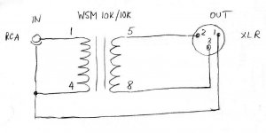
Peter Daniel said:This is how I had Edcor transformer wired to convert unbalanced signal into balanced, to use with LM4780 in bridged mode.
that simple! i'll give it a go
-ben
Coaxial copper
Ok, I'm a beginner.
What about the copper of a coaxial cable for ground bridge?
I also found an anamel copper from a transformer. Is it better?
CAT5 copper for R1 bridge is ok or standard awg wire is preferred?
Thank you very much for your work and sorry for my very bad english.
Ok, I'm a beginner.
What about the copper of a coaxial cable for ground bridge?
I also found an anamel copper from a transformer. Is it better?
CAT5 copper for R1 bridge is ok or standard awg wire is preferred?
Thank you very much for your work and sorry for my very bad english.
- Home
- More Vendors...
- Audio Sector
- Commercial Gainclone kit- building instructions