The position of volume control is not critical. It’s probably due to low efficiency of the speakers. If you have a choice between 10k and 50k potentiometer, the first one would be more suitable.
For proper perspective on volume control settings, read first two paragraphs of this article: http://www.firstwatt.com/pdf/art_b1_man.pdf
For proper perspective on volume control settings, read first two paragraphs of this article: http://www.firstwatt.com/pdf/art_b1_man.pdf
Sigh (me swooning)
Incredible diy
Incredible diy
Hi Everyone,
This is my Gainclone build using Peter's excellent PCBs.
I'm really happy how it came together in the end and it sounds really great.
More info on my blog if you are interested. www.jeremyyoungdesign.com
Hi Everyone,
This is my Gainclone build using Peter's excellent PCBs.
I'm really happy how it came together in the end and it sounds really great.
[/URL]
Sensational workmanship!
Normal as the only gain stage is the amp itself.
Sigh (me swooning)
Incredible diy
Thanks guys.
The position of volume control is not critical. It’s probably due to low efficiency of the speakers. If you have a choice between 10k and 50k potentiometer, the first one would be more suitable.
For proper perspective on volume control settings, read first two paragraphs of this article: http://www.firstwatt.com/pdf/art_b1_man.pdf
Yeah I see your point about the position of the volume knob not being critical, I am aware that it is really quite arbitrary. I guess it just felt like I might be pushing the amp too hard, perhaps it's just a psychological thing and I need to get used to running it with the knob wound up.
Cheers,
Jeremy
Last edited:
Hello Gentlemen! Almost finished (still without enclosure) but already checked and it works perfectly! Peter, thank you once again! Now I'm going to make a dual mono, so will order another set soon )))
An externally hosted image should be here but it was not working when we last tested it.
An externally hosted image should be here but it was not working when we last tested it.
An externally hosted image should be here but it was not working when we last tested it.
Outstanding work! Perfectly build! Congrats!Hi Everyone,
This is my Gainclone build using Peter's excellent PCBs.
I'm really happy how it came together in the end and it sounds really great.
More info on my blog if you are interested. www.jeremyyoungdesign.com
Some LM3875 Kit Building Questions
These questions relate to the Instruction PDF which is also the first posts to this thread by Peter Daniel.
Q1. Peter says he leaves out the optional R1. In the images in the instructions I see it's installed. Should I leave it out and if so is this just replaced with a wire?
Q2. The Diagram of a dual Voltage transformer in the instructions is shown below
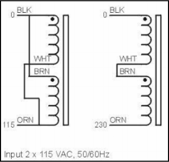
For a 230 VAC supply as in NZ the primaries are joined.
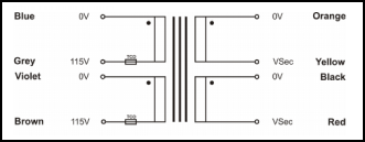
This is the diagram below of my actual transformer below. DO I JOIN GREY AND VIOLET for a 203VAC supply

Q3. I have read through the build instructions and images carefully but no actual connection diagram seems to be here. Can anyone confirm that my diagram below is as described Peters build instructions

Cheers
Maak Bow
These questions relate to the Instruction PDF which is also the first posts to this thread by Peter Daniel.
Q1. Peter says he leaves out the optional R1. In the images in the instructions I see it's installed. Should I leave it out and if so is this just replaced with a wire?
Q2. The Diagram of a dual Voltage transformer in the instructions is shown below
For a 230 VAC supply as in NZ the primaries are joined.
This is the diagram below of my actual transformer below. DO I JOIN GREY AND VIOLET for a 203VAC supply
Q3. I have read through the build instructions and images carefully but no actual connection diagram seems to be here. Can anyone confirm that my diagram below is as described Peters build instructions
Cheers
Maak Bow
Attachments

Q3: That's a very nice diagram, everything is correct here, except that audio ground (common point for power ground wires) connect to the chassis through 10R 3W resistor.
Q2: That would be corect'
Q1: I usually recommend bypassing R1 with a jumper on Premium kits where improved sound quality is expected. For regular kits, you can leave it in.
Q2: That would be corect'
Q1: I usually recommend bypassing R1 with a jumper on Premium kits where improved sound quality is expected. For regular kits, you can leave it in.
Thanks so much for the answers Peter.
With regards to the 10R 3W resistor where audio ground connects to chassis.
Is this what is known as a "Break Resistor"?
I don't see it anywhere in the instructions or images though I'm happy to do what you recommend as I'm the noob here. This is the first time I've built a kit where I create the power supply, so I'm making sure I am super confident I'm doing it right before I build, connect up and test.
Can you explain what this resistor does? Is it to help eliminate ground loops?
PS. The diagrams are created in FIGMA figma.com. An excellent intuative browser based digital design application with a free plan... that works for creating diagrams also.
The reason it's done like that is because typically the chassis is also connected to the AC safety ground. Tying your signal/power supply ground directly to the chassis may result in ground loop problems. A resistor simply reduces the inter chassis current a bit and helps reduce ground loop noise. The actual value is not critical
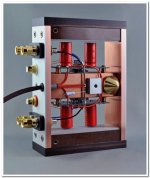
You can see that resistor in this picture.
You can see that resistor in this picture.
Attachments
Thanks for the explanation Peter. A beautifully made amp there.
General Question for anybody re amp enclosure Shielding and wiring
I'm aware that often it's said that there may be no issue with anything next to anything. However, I'm building my own case anyhow so having metal next or around certain objects may be no issue for me.
So ideally or even theoretically...what parts should be shielded from what? I've read that AC should kept from DC, If so what about the rectifier that has both? What part should be enclosed? the transformer?, AC input? or the amp?.
And what cables can benefit from being twisted?
I’ve built amps where transformer was right beside amp boards and didn’t experience any issues. In general I would avoid mixing AC power cables and input signal wires. I usually don’t twist anything as all my connections are made as short as possible.
Input signal wires would benefit most from twisting though.
Input signal wires would benefit most from twisting though.
I'm just about to hookup my boards.
Peter, what's the idea behind solid wire over stranded for the input connections. Is there a theory or opinion that it sounds better?. I have a tin coated solid copper wire. I'm pretty sure I can get my input and output wire really short
Also does anyone have an opinion on putting the power switch on the front vs the back. The back is easier as I have an all in one socket fuse switch, but the front seems more practical somehow.
Hi Peter
So I've connected Up the transformer and rectifier and these are the measurements. I think they are ok.
AC is coming in at 229VAC
The transformer is 300VA 24V
AC1 is reading 25.4VAC
AC2 is reading 25.5VAC
V- PG- reads -25.8
V+ PG+ reads 22.3
LED lights
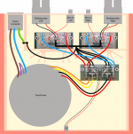
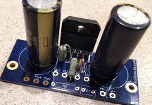
Do the amp boards look correctly populated (below). If so i will connect to the rectifier and test. I only have DMM to test so cannot generate sine waves. Is there another way to do this test?.
Also I have nothing to create a dummy load here, can I just use a crap 8Ohm 40W driver I have lying around or is that not wise?
So I've connected Up the transformer and rectifier and these are the measurements. I think they are ok.
AC is coming in at 229VAC
The transformer is 300VA 24V
AC1 is reading 25.4VAC
AC2 is reading 25.5VAC
V- PG- reads -25.8
V+ PG+ reads 22.3
LED lights
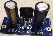
Do the amp boards look correctly populated (below). If so i will connect to the rectifier and test. I only have DMM to test so cannot generate sine waves. Is there another way to do this test?.
Also I have nothing to create a dummy load here, can I just use a crap 8Ohm 40W driver I have lying around or is that not wise?
Attachments
It is rectified AC voltage, but since there no smoothing caps on rectifier board, the ac reading is low. You will see normal readings when amp boards are connected to rectifier boards and smoothing caps engaged.
After power supply is connected, check the DC offset first, it should be less than 80mV or so. If that’s the case, you can hook up your crappy driver for further testing.
Each wire will have different sound characteristics, just use whatever you have available. For signal input 24ga or less is recommended. There’s no rule that solid core sound better than stranded, your preference will come from testing and listening. Some people don’t hear the difference at all, so here you go ;-)
As to power switch, put it where it’s most convenient. I usually don’t switch off my gainclones at all, so power switch is at the back.
- Home
- More Vendors...
- Audio Sector
- Commercial Gainclone kit- building instructions