It does not matter. This link ONLY passes Fault Current when there is a catastrophic mains failure inside the amplifier. During normal operation it should not pass any current. You can connect any point on the Main Audio Ground to the chassis at that point. You don't need to take it to the mains PE, I don't recommend that you use a long wire. You will probably not need a Ground Loop Breaker (Disconnecting Network) in a monoblock amplifier. Because there is no loop between the ONE channelHi !
Thanks !
uhm... two ( for me very important ) questions:
1. To which pad on the amp board should I connect chassis ground ?
Try without. You can add it later, if further experiment proves that it is required.. This chassis wire may pass some interference current. But it should NOT pass any audio current.
2. I have understood that a ground break circuit is preferable? - but will I maybe manage without? I really want these two amplifiers to sing today...
Thank you !
Have you read D.Joffe article?
He clearly shows this is an inter-channel problem in multi-channel amplifiers. He does not explicity state so, but this affliction also applies to pre-amps that contain more than one channel.
Last edited:
one amp reconfigured. finally.
one to go...
NO hum this time.
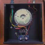
but still some very low radio frequencies are coming from the speaker.
this time it is so low that maybe putting on the chassis top-panel will make it dead quiet?
* picture attached.
should I shorten down the cable going from the MEM ground to chassis?
green/yellow wire connected to chassis : is connected to signal ground pad on the side not seen on this picture.
Thanks for all help so far- it definitely has been a long quest for me; this exact amp build. the amp sounds really REALLY good.
one to go...
NO hum this time.
but still some very low radio frequencies are coming from the speaker.
this time it is so low that maybe putting on the chassis top-panel will make it dead quiet?
* picture attached.
should I shorten down the cable going from the MEM ground to chassis?
green/yellow wire connected to chassis : is connected to signal ground pad on the side not seen on this picture.
Thanks for all help so far- it definitely has been a long quest for me; this exact amp build. the amp sounds really REALLY good.
Attachments
try to find a piece of Green/Yellow cable and replace that green cable from PE to Chassis.
Green lloks too much like a ground and could confuse some less experienced Builder that looks inside.
What are the two yellow wires that disappear under the IEC?
Green lloks too much like a ground and could confuse some less experienced Builder that looks inside.
What are the two yellow wires that disappear under the IEC?
have you fitted an RF attenuation Filter to the input?
No, I have not fitted any RF attenuation filter to the input. Should I do so?
The two yellow wires are the two power wires going to the toroidal transformer.
they were originally one layered ( white in color ) , I put on sleeves for safety reasons.
The two yellow wires are connected to the end of the MEM - with ON/OFF switch / fuse holder and a IEC socket on the top.
The two yellow wires are the two power wires going to the toroidal transformer.
they were originally one layered ( white in color ) , I put on sleeves for safety reasons.
The two yellow wires are connected to the end of the MEM - with ON/OFF switch / fuse holder and a IEC socket on the top.
Double insulate the mains wiring.
Since the aluminium case looks to be anodised, (a very good electrical insulator) I suggest you interlink some of the panels with bolted connections and stranded insulated wire.
Maybe the back panel to the side panel, next to the IEC and the floor panel under the IEC. These three panels are the highest risk, if a mains wire breaks loose.
Twist the mains wiring to reduce emi.
Twist the two sets of secondary wires.
Reduce the size of the loops in the audio in out wiring.
Are there any instructions in your Builder's guide relating to interference?
Last edited:
I have used long twisted pair interconnects in unbalanced connections in many orientations around, over, under transformers and along along mains cables, even those feeding digital components and could not hear any deterioration in the output at the amplifier.I would also move the input wires as far away as possible from the transformer, they appear to almost touching the transformer.
I also tried star quad as long interconnects using the same rigorous subjective testing and again found no deterioration.
As a result I have become a firm believer is LOW LOOP AREA as one of the best ways of minimising interference. And recommend it to Members (repeatedly).
Maybe I should repeat that experiment and MEASURE the HUM+NOISE at the output.
I have used long twisted pair interconnects in unbalanced connections in many orientations around, over, under transformers and along along mains cables, even those feeding digital components and could not hear any deterioration in the output at the amplifier.
I also tried star quad as long interconnects using the same rigorous subjective testing and again found no deterioration.
As a result I have become a firm believer is LOW LOOP AREA as one of the best ways of minimising interference. And recommend it to Members (repeatedly).
Maybe I should repeat that experiment and MEASURE the HUM+NOISE at the output.
Andrew, Your advice is, as always, sound and practical. I would agree that a well constructed (tightly) twisted pair offers very good immunity to interference. Nonetheless, I consider that routing signal cables away from transformers and mains cables is good practice.
Your advice regarding making good connections to anodised components is something that often causes problems to the unwary, I usually use tapped holes or self tap screws to ensure continuity.
Hi !
Thanks !
uhm... two ( for me very important ) questions:
1. To which pad on the amp board should I connect chassis ground ?
2. I have understood that a ground break circuit is preferable? - but will I maybe manage without? I really want these two amplifiers to sing today...
Thank you !
CHG => Chassis Ground
Maybe I should repeat that experiment and MEASURE the HUM+NOISE at the output.
TEST of one monoblock:
HUM+NOISE at the output ( speaker terminals ) = 1.2mV AC
I have no longer any issues with radio frequencies :
* twisting and double isolating the two wires going from the MEM to the transformer.
* rearranging the signal + signal ground wire ( shortening the wire + twisting the wires + installing the RCA on the front panel )
* rearranging both speaker terminals ( shortening the wires + installing both speaker terminals in front )
1.2mV AC is too much - what to do next?
PS: I have a 2X25V , 300VA transformer. Chassis Ground is still connected to SG ( signal ground ) - NOT the CHG pad.
Last edited:
I consider >1mVac as too much.
I expect every power amplifier to be <0.3mVac and most of mine are <0.1mVac
using cheap and more expensive DMM set to 199.9mVac
1.2mVac compared to 0.1mVac is +21.6dB
a reading of 0.0mVac is really <0.05mVac and 0.05mVac is -27.6dB ref 1.2mVac
I expect every power amplifier to be <0.3mVac and most of mine are <0.1mVac
using cheap and more expensive DMM set to 199.9mVac
1.2mVac compared to 0.1mVac is +21.6dB
a reading of 0.0mVac is really <0.05mVac and 0.05mVac is -27.6dB ref 1.2mVac
A friend of mine sells an audiosector LM3875 based (the premium circuit) two monoblocks, each one uses a 400VA/2x24v transformer, custom/locally made. These amps sound very accurate and precise, are very snappy, clear and bright with lots, lots of details. I still prefer listening with my old Quad 405 to some stuff, as it's more musical - much less detailed and very spongy compared to the chipamp though. My friend asks for about 520$ for the two blocks, saying that was the original cost of the parts. I still wonder what would it sound like if I used a cheap, Chinese made transformer for the two channels, building one for half the price (or less). 520$ sounds quite high to me considering the part (not including the transformer) are 100$... what do you think ? and are there better choices for the chipamp in that price range, for something which is as clear and detailed sounding ?
62k resistor any other values matter?
Hi total Newb compiling a parts list for my first GC amp build, question is, as I search for a 62k resistor I'm wondering if wattage values matter, tolerance values matter using the exact LED as described above.
If a link to exact resistor to buy can be posted that would be great.
Thanks.
There is a spot for a LED on rectifier board and I like the small Panasonic LEDs available from DigiKey (part# P612). With those LEDs, 62K series resistor is required (R3 on rectifiers board, the long pin from the LED connect to square pad).
So the transformer is connected; before connecting rectifier board to the amp board we need to test voltages first.
If you didn't make any mistake, the simple test would be observing if LED lights up properly, but I will describe more appropriate method tomorrow")
Hi total Newb compiling a parts list for my first GC amp build, question is, as I search for a 62k resistor I'm wondering if wattage values matter, tolerance values matter using the exact LED as described above.
If a link to exact resistor to buy can be posted that would be great.
Thanks.
So just to verify due to my ignorance, like this one here?
20 Pcs 62K Ohm 62 000R 5Watt Metal Film Resistors 5W Resistor 1 4587 | eBay
20 Pcs 62K Ohm 62 000R 5Watt Metal Film Resistors 5W Resistor 1 4587 | eBay
- Home
- More Vendors...
- Audio Sector
- Commercial Gainclone kit- building instructions