Cost of a 3 channels setup
Hi Ellis,
According to my two channels setup, with a case large enough for 3 channels:
Case 1x : 42 EUR
R-Core transf. 3x : 270 EUR
Heatsink 30 cm 1x : 30 EUR
Fused mains inlet: 4 EUR
Noble VC 1x : 40-50 EUR
Peter's premium kit 3x : 135 EUR (98 US$ for a stereo premium kit)
Of course, it's premium parts with premium kit; it could be made less expensive.
Hope this helps.
Alain
Thanks Alain.
Now to see if i can find someone who would be willing to build me a 3 channel with gain controls, and balanced inputs, and outputs (if that is possible).
tia,
Ron
Question about dc offset
Hello Peter and all
Disclaimer: I am a complete NOOB...a NOOB that has been lurking on here for 7 years, but still a complete NOOB. The only thing I know is that I know nothing at all...except what I try to convince myself that I understand on these forums. Oh...and I'm long winded.
Finally after about two years of "tinkering" on the kitchen table, and various other locations, I have a potentially finished gainclone based on Audiosector's premium LM3875 kit. I tried to keep this, my first amplifier build, as simple as possible.
I have done my best to follow the build instructions and research my questions along the way. However, now that I have the amp assembled and have been testing the power supply and the DC offset before trying to use the amplifier with speakers, I am left with a question about the results of my DC offset measurements which I have taken under several conditions.
The power supply appears to be functioning fine. I am using a 24 volt torroid that I sourced from Apex Jr. It is producing about 34 volts at the rails on the rectifier board.
When I powered up the power supply and then the amp completely assembled I did so with a variac I purchased from a fellow member. I was cautious and brought the power up very gradually.
My first observation with the amp completely assembled was that my DC offset measurement on the channel my DMM was connected to was producing much larger numbers than I expected. As I increased the power supply to 30% or so and my LED came on for the amp's power supply I noticed as much as 4 or 5 volts of DC.
Strangely enough, the DC voltage seemed to reach a threshold when I approached 40-50% on the variac scale and it began reading in millivolts.
Unfortunately, the measurement was still as high as a couple hundred millivolts. It was also measuring as negative. The measurement was fluctuating constantly. It appeared to be decreasing very gradually if I didn't increase power at the variac. I tried increasing power, and the offset would increase but continue to behave the same way. Out of concern, I decided to power down the amp and try testing the other channel. Although the numbers were different, it behaved the same as the first.
I did some head scratching and a bit of research on decibel dungeon and various threads on here. I then attempted the same power up approach with a 10 Ohm 10 watt resistor across the binding posts of the amps channels. I got slightly lower readings, but nothing close to what I had read I should be measuring. I noted that the longer I was working on the amp powered up even at 50% the lower the DC offset was ever so slowly drifting with or without the resistor mounted on the binding posts. Both channels behaved the same with slightly different results.
Since nothing had blown up YET and I didn't have any speakers connected, I decided to try and power the amp up to 100% and see what the bottom line was on the offset readings. I tested with and without the 10 Ohm resistor across the binding posts. One channel was as high as -250mV when first powered up without the resistor installed. After about 10 or 15 minutes I measured about -160mV on one channel and -80mV on the other with no resistor installed. A few minutes later I got -153 and -70 with the resistor installed. After I allowed the amp to sit powered up for about an hour the offset numbers seemed to be fluctuating and creeping down much less. One channel measured -116mV and the other measured -46mV with the resistor still installed.
More reading and review of the Manual and Peter's testing notes. I picked up on his comment about the approximate 4 volt jump in DC offset during power up/down and that it did not occur when a load was across the binding posts. I tested my amp and confirmed the voltage jump didn't occur with my load resistor installed across the binding posts.
Another thread prompted me to revise the layout of my power star ground. There was no difference in DC offset.
I came across a few other threads concerning DC offset issues with gainclones. None of them seemed to be the same exact issue as mine. One mentioned a problem with very high DC voltage (35 volts) with no input connected on a non-inverted version?
I scratched my head yet again and realized I hadn't tested the amp with anything connected to the input or with the input "shunted" or grounded. Really, I had assumed I was to avoid connecting anything to the amp in any way before it was proven to be safely operating? Another look at the build instructions and I saw Peter was testing the amp with the input shunted to ground and getting very low DC offset numbers.
I connected an old shorted RCA plug to the inputs on the amp and Viola!...I took a measurement of -6.4 mV on one channel and 2.2 mV on the other. I retested with a good stereo RCA adapter cable running from my old iPhone into the amp. DC offset was within a few mV of the input being grounded.
So what's my problem? Well, I can't seem to find any information specific to the issue of having such high DC offset numbers when I have no input connected to the amp. Is this normal? Will it damage my speakers? Do I have to make sure I never power the amp up with speakers connected when there is no source connected to it? Do I have a problem with this amp that needs further diagnostic and a solution to improve the offset numbers with no source connected?
Thanks for your patience and any feedback.
Kevin
There are many warnings on this Forum about building and using DC coupled Power Amplifiers.
Audio Sector uses a DC coupled arrangement.
One of the consequences is higher than usual output offset.
A second consequence is a change in output offset when the input/Source conditions are changed.
Your description fits exactly with both of these.
You as User has to decide whether to carry on with Audio Sector's philosophy, that brings with it the increased risk of excessive output offset.
The drift in output offset that you have seen may be due to some of the electrolytic capacitors reforming while in circuit. Electrolytic capacitors leak. They leak a bit after reforming. They leak enormously if not reformed since manufacture.
These natural leakage currents are equivalent to adding a bypass current around the DC blocking capacitor.
That leakage current gives different DC conditions and as leakage reduces the DC conditions change. This is likely to be the drift to lower offsets that you have measured.
Reforming all your electrolytics prior to building would have eliminated this excessive leakage problem.
Andrew
Thanks very much for your response here and in my repost in the Chip Amp section.
I encountered several threads where you have recommended that beginners are better off working with AC coupled power supplies. I suppose if I had understood the difference between AC and DC coupled designs I might have made that choice.
My goal when I first came to DIY was to see if I could get help and figure out how to repair some audio equipment I had purchased that was damaged or not working properly.
When I realized that I had so much to learn, and began to look around for a way to accomplish that, it was the simplicity and great support and documentation of this project that made me put aside those repairs and even aspirations to build an F5 amplifier...temporarily.
Now that I understand that the test results I got with this amp are "the nature of the beast" I can move forward. I will be testing the DC offset of any different sources I want to use with this amp prior to connecting any speakers to it and will make sure I don't power up the amp with speakers connected without a source connected or the input grounded.
Perhaps in the future I may want to explore whether I can or I want to apply some kind of DC filtering.
Thanks very much for your help.
Kevin
So what's my problem? Well, I can't seem to find any information specific to the issue of having such high DC offset numbers when I have no input connected to the amp. Is this normal? Will it damage my speakers? Do I have to make sure I never power the amp up with speakers connected when there is no source connected to it? Do I have a problem with this amp that needs further diagnostic and a solution to improve the offset numbers with no source connected?
The offsets are normal: 160mV with no input connected is a bit high and happens rather rarely, but some chips will produce that much offset in this configuration.
When a source is connected the offset will usually go down.
I explained many times before, using coupling cap will not help here with the offset, it will actually prevent of the offset to be reduced.
One way to reduce offset from a chip is to install smaller value of input shunt resistor: 10K instead of 22k for instance.
Fluctuated offset up to 4V or so with no load connected and powering with Variac is normal too.
Oh the noise noiSE nOISE NOISE
Hello Peter
Thank you for taking the time to respond. I'm grateful for the help that is always offered on these forums.
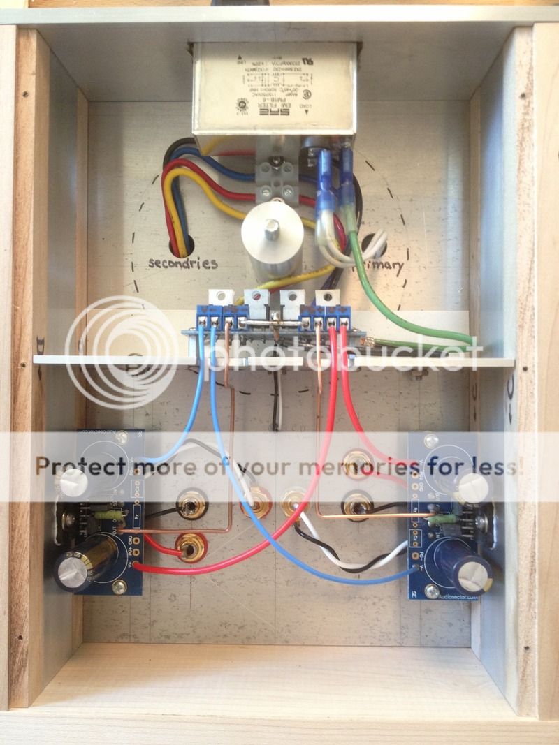
This evening I did my first tests and listening with my amp that I posted a pic of above.
I hooked up a cheap pair of little Aura drivers I picked up on clearance at Madisound a while ago to one channel first. I had to wire up two speakers to get an 8 Ohm load.
When I powered up I was plugged into the variac and had my iPhone connected to the input on the amp via a cheap mini stereo to RCA adapter cable.
Noise was immediately audible before I turned up the volume and played any music. I've had nightmares with noise and amps before...and I wasn't able to solve them then. The noise is present in both channels of the amp under the same test circumstances.
Whether its hum or ripple? I don't know. My understanding is that each tends to make noise at a specific frequency range. This noise sounds like a dull midrange buzzing.
The noise didn't stop me from listening. Once I saw my test speakers didn't blow up I decided to hook the amp up to my semi-assembled front horn project I've also been working on for a while. It's a pair of used Oris 200 horns I got in the swap meet here cheap with a pair of Tang Band 1808 mounted in them with an unsealed rear chamber. I half hoped the noise would be eliminated by using a different power source, input source or speakers...it didn't.
All I used for a source was my iPad streaming Pandora playing some of my favorite female jazz vocalists on the higher quality sound setting with the same cheap adapter cable.
The speakers are shouty to begin with. I set what seemed like a good volume to over come the amp noise (which is audible to the back of my 20 ft deep living room) and temper the shout.
Honestly, even with so many issues influencing my listening experience...I still found my smile growing more and more as I listened. The funniest part of all is that my amp smiles back at me because of a silly face pattern the power LED casts on the tranny cover mounted to its top plate. There were a few haunting holographic fun moments. In between tracks was annoying noise.
So now I think I need to take another look at my grounding, which I had already revised to what I thought was a fairly accurate reproduction of the power ground star method illustrated in the build guide...but perhaps not? If anyone could comment on this noise issue and/or my ground wiring based on the image I attached previously I would be thankful.
The only other test I thought I should try was to connect a speaker to one channel at a time on the amp, shunt that channels input to ground and power up the amp to listen to that channel for noise. Under those circumstances there is absolutely no noise coming from the speakers/amp.
Kevin
Hello Peter
Thank you for taking the time to respond. I'm grateful for the help that is always offered on these forums.
This evening I did my first tests and listening with my amp that I posted a pic of above.
I hooked up a cheap pair of little Aura drivers I picked up on clearance at Madisound a while ago to one channel first. I had to wire up two speakers to get an 8 Ohm load.
When I powered up I was plugged into the variac and had my iPhone connected to the input on the amp via a cheap mini stereo to RCA adapter cable.
Noise was immediately audible before I turned up the volume and played any music. I've had nightmares with noise and amps before...and I wasn't able to solve them then. The noise is present in both channels of the amp under the same test circumstances.
Whether its hum or ripple? I don't know. My understanding is that each tends to make noise at a specific frequency range. This noise sounds like a dull midrange buzzing.
The noise didn't stop me from listening. Once I saw my test speakers didn't blow up I decided to hook the amp up to my semi-assembled front horn project I've also been working on for a while. It's a pair of used Oris 200 horns I got in the swap meet here cheap with a pair of Tang Band 1808 mounted in them with an unsealed rear chamber. I half hoped the noise would be eliminated by using a different power source, input source or speakers...it didn't.
All I used for a source was my iPad streaming Pandora playing some of my favorite female jazz vocalists on the higher quality sound setting with the same cheap adapter cable.
The speakers are shouty to begin with. I set what seemed like a good volume to over come the amp noise (which is audible to the back of my 20 ft deep living room) and temper the shout.
Honestly, even with so many issues influencing my listening experience...I still found my smile growing more and more as I listened. The funniest part of all is that my amp smiles back at me because of a silly face pattern the power LED casts on the tranny cover mounted to its top plate. There were a few haunting holographic fun moments. In between tracks was annoying noise.
So now I think I need to take another look at my grounding, which I had already revised to what I thought was a fairly accurate reproduction of the power ground star method illustrated in the build guide...but perhaps not? If anyone could comment on this noise issue and/or my ground wiring based on the image I attached previously I would be thankful.
The only other test I thought I should try was to connect a speaker to one channel at a time on the amp, shunt that channels input to ground and power up the amp to listen to that channel for noise. Under those circumstances there is absolutely no noise coming from the speakers/amp.
Kevin
Chromenuts, you have placed the star GND between the PSU, where it should be placed is between the AMP boards with PG+ and PG- of the PSU board separately connecting to the star.
A few things to try are disconnecting the PE from the star GND, moving the transformer away from the amp boards and a potentiometer at the inputs so that you can set the digital volume of the source to full.
A few things to try are disconnecting the PE from the star GND, moving the transformer away from the amp boards and a potentiometer at the inputs so that you can set the digital volume of the source to full.
Big smiles
Thanks Mark and everyone for your responses.
Sometimes you need someone to say out loud what you're thinking.
I knew that I had been trying too hard to get the ground wiring to work with my chassis layout decisions. As I mentioned, I had already changed it once. I changed the ground wiring again today and finally got it right.
It's not as pretty as I wanted it, but I guess sometimes physics is more important than aesthetics?
The amp is dead silent now to my ears in between tracks...and it plays wonderfully through my half-finished front horns.
I've spent some good time this evening smiling in front of my HiFi...heck, my wife even said it sounds good!!!
I'm looking forward to posting in the chip amp pic thread.
Onward and upward!
Kevin
Hello,
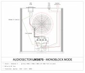
I have built myself a pair of monoblocks of the LM3875 kit.
I have used star ground in both monoblocks. ( see attached layout )
I´ve run into some trouble with my kit:
1. There is interference of radio frequencies in both monoblocks when speaker connected ( especially with a preamp and source signal connected; this only increases the radio signal . )
2. I also am quite sure I´m having trouble with ground loops in my setup ( especially when used with a Quad 44 pre and 500mV output. )
QUESTIONS :
1. Where to start the measuring of my two amplifiers? Further measurements?
2. Especially the last built monoblock have a amplimo toroidal transformer that makes quite some noise when turned on and afterwards when playing music - normal?
PS: I will later on today put up pictures of my LM3875 monoblock build. First off I will try what happens when using the pre section of a NAD 3120 amplifier.
Attachments
MY TIME WENT OUT TO EDIT...
Hello,
I have built myself a pair of monoblocks of the LM3875 kit.
I have used star ground in both monoblocks. ( see attached layout )
I´ve run into some trouble with my kit:
1. There is interference of radio frequencies in both monoblocks when speaker connected ( especially with a preamp and source signal connected; this only increases the radio signal . )
2. I also am quite sure I´m having trouble with ground loops in my setup ( especially when used with a Quad 44 pre and 500mV output. )
BOTH ISSUES ADRESSED ABOVE WAS CONNECTED TO THE USE OF THE QUAD 44 PRE. WHY DO YOU THINK SO?
QUESTIONS :
1. Where to start the measuring of my two amplifiers? Further measurements?
2. Normal that a toroidal transformer makes a little bit noise that can be heard from the chassis when turned on and afterwards when playing music ?
BOTH AMPS NOW MAKES A A HIGHER PITCHED HUM ( - THAN GROUND HUM ) - BOTH HIGHER PITCH HUMS COMES FROM BOTH SPEAKERS - WHAT IS CAUSING THIS ISSUE?
BOTH AMPS STILL TAKE IN RADIO FREQUENCIES
PS: I will later on today put up pictures of my LM3875 monoblock build.
Last edited:
Hi,
"Ground to Chassis" it's not correct, see page 30 :
http://www.audiosector.com/nigc_kit-users_guide.pdf
Input and output wires are twisted ?
Phil.
"Ground to Chassis" it's not correct, see page 30 :
http://www.audiosector.com/nigc_kit-users_guide.pdf
Input and output wires are twisted ?
Phil.
I follow Mark advices :A Ground Loop Breaker can also be inserted in this connection.
http://www.diyaudio.com/forums/chip-amps/271984-lm3875-chipamp-4.html
Schematic :
http://www.diyaudio.com/forums/chip-amps/265827-lm3886-fullrange.html
Phil.
Hi !
Thanks !
uhm... two ( for me very important ) questions:
1. To which pad on the amp board should I connect chassis ground ?
2. I have understood that a ground break circuit is preferable? - but will I maybe manage without? I really want these two amplifiers to sing today...
Thank you !
Thanks !
uhm... two ( for me very important ) questions:
1. To which pad on the amp board should I connect chassis ground ?
2. I have understood that a ground break circuit is preferable? - but will I maybe manage without? I really want these two amplifiers to sing today...
Thank you !
takes me to post41I follow Mark advices :
http://www.diyaudio.com/forums/chip-amps/271984-lm3875-chipamp-4.html
takes me to post1
have you fitted an RF attenuation Filter to the input?Hello,
I have built myself a pair of monoblocks of the LM3875 kit.
I have used star ground in both monoblocks. ( see attached layout )
I´ve run into some trouble with my kit:
1. There is interference of radio frequencies in both monoblocks when speaker connected ( especially with a preamp and source signal connected; this only increases the radio signal . )
What are your symptoms?2. I also am quite sure I´m having trouble with ground loops in my setup ( especially when used with a Quad 44 pre and 500mV output. )
Have you measured Hum+noise at the amplifier output for the various operational modes? (vol pot at minimum, vol pot at maximum, vol pot removed and dummy load plugged into the input)
insert a dummy zero ohms load into the input. Measure output offset using 199.9mVdc scale of your DMM.QUESTIONS :
1. Where to start the measuring of my two amplifiers? Further measurements?
Measure output Noise+Hum using 199.9mVac scale of your DMM.
Connect your pre-amp/vol pot and repeat both measurements with vol pot at min, at max and midway.
Connect your source, but muted or switched off and repeat measurements.
Two different amplimo transformer that perform differently. Is one faulty? Is one worth complaining to your retailer and asking for a replacement at their cost?2. Especially the last built monoblock have a amplimo toroidal transformer that makes quite some noise when turned on and afterwards when playing music - normal?
PS: I will later on today put up pictures of my LM3875 monoblock build. First off I will try what happens when using the pre section of a NAD 3120 amplifier.
- Home
- More Vendors...
- Audio Sector
- Commercial Gainclone kit- building instructions