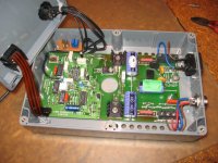
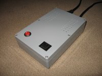
Well I finally finished my two speed Valhalla for my Linn and so far it works great and sounds even better. I had been wanting to play 45's on my Linn for quite sometime but I have always hated the adapter pulley so I've always played my 45's on an old Ariston RD-11S. 45 Singles have always been of mediocre quality so it really didn't matter. However very high quality 45 LP's are much more common now and I wanted to play these on the Linn. At the beiginning of the year my Valhalla suddenly died and I was forced to repair it. Not bad really considering it has been powered up since 1988. Thanks to the forum I was able to get a schematic. After realizing how simple the circuit it was, I decided to make a 45 rpm version. I purchased another Valhalla on eBay and mounted both boards externally in a separate case from my Linn. I wasn't very impressed with the power supply on the Valhalla. For 240V users it has a full wave rectifier filtered through two 47uF caps. For 110V user like myself it uses a voltage doubler circuit to obtain the 320V DC high voltage supply. Despite the low current requirements this is still not a very clean power supply so I built a separate power supply to power both boards using 110-240V transformer with rectifier bridge and 600uF filter cap. I also built a separate regulated 10V power supply for the low voltage circuit. I then added simple switching to allow easy changing for both speeds. I just finished it tonight and have been listening ever since. I think the better power supply has definitely helped with reducing motor vibration and the the sound stage has openned up and deepened. It reminds me of when I first heard a Lingo/Valhalla comparison but not nearly as dramatic. I am definitely happy with the improvment.
Seems like a very inefficient way to utilise a second board. For 45 you just need a second oscillator. Maybe even switching to a different crystal will do the job.
A much cooler application for the second Valhalla will be to build a separate oscillator board, switchable between 33/45 and able to generate a second phase as well. Now you can use the second board to amplify the other phase and take out the motor phase cap.
A much cooler application for the second Valhalla will be to build a separate oscillator board, switchable between 33/45 and able to generate a second phase as well. Now you can use the second board to amplify the other phase and take out the motor phase cap.
I tried that but switching to a different crystal changed the amplitude of the output signal of the square wave and I had to reduce the resistance to get the correct output voltage. The highest output voltage I could achieve was 72V at 45 rpm at the lowest resistor setting on the original Valhalla board. At 33 1/3 the same resistor setting produced 115V. Either way I needed to able to generate two differnet signals and adjust their output levels independently. It certainly is possible to build an add on board for the second signal and graft it in the original Valhalla board but with two simple part exchanges on another Valhalla board I had a fully functional 45 rpm output.
I can certainly appreciate there are much better modern techniques to generate sinewaves, but my goal was to get the second speed in a quick and easy fashion. Had I wanted to start from scratch I would probably want to use the new programmable MPU's to generate a clean sine wave with a minimum of filtering. They also allow you to accurately generate the second phase. What I am not clear on is the actual benefit of creating the phase shift actively through registers versus passively with a capacitor. The capacitor creates the 90° phase lag needed. Moreover I believe the the secondary windings on ac sychronous motors are designed to be impedanced matched with primary windings using the a specified capacitor so you would need to compensate for this also.
I actually bought a used Axis on eBay with that in mind. I rebuilt the ps to ensure full output first. First problem is mounting. I don't know that it can mount inside a LP-12 with that large heatsink. On the Axis there is a large slot cut out of the plinth to pass the heatsink through. The other thing I found out is that the power supply only generates 70V at startup and then drops down to about 25V at quiet mode. The platter on a Axis is considerably lighter than on an LP-12. The power supply will not free start the table loaded with my non-Linn record mat, you have to give it a boost to get it started. After that the load sensing circuit will adjust output voltage to maintain the correct speed. The other alternative would be the late model Valhalla used on both the Axis and LP-12 but you don't see those for sale very often. There is an after market version called the Hercules II which is basically a Valhalla board with two crystal generated signals that can be switched via the start button. It is about $375 though. Anyways when I put an arm and cartridge on the Axis it turned out to be a pretty decent sounding table so I it now replaces my old Ariston RD-11S with the noisy motor.
Changing a Valhalla to run at 45 rpm is very simple. You need to change the crystal oscillator to 4.433 MHz. The original crystal is 3.2768 MHz. Then you need to change R13 from 22K to 15K to give a bit more output because the low pass filter is optimized for 50Hz. The Valhalla will now output 67.5Hz which will give you 45rpm.
I know this is a very very old thread, but I'm interested in modifying a Valhalla to provide 45 as well as 33 as mentioned by tkwou.
I am currently using an upgraded Valhalla in a separate box to power my AR The Turntable.
My plan is to lift the standard crystal and resistor off the circuit board and use a double switch to select the appropriate combination for either of the two speeds.
Has this been done as suggested by tkwou above, and if so how successfully.
cheers
Graham.
It's been ages since i last had a Linn or a Valhalla, but here is what i would do today. The entire concept of generating a square wave and then forcing it into looking like a sine may have been appropriate 30 years ago but motors run better on clean sinewaves.
Lots of readily available solutions on Ebay which provide DDS generated sinewaves of astonishingly low distortion. Effectively this means keeping only the Valhalla high voltage amp and disabling the onboard oscillator and filter.
One option will be to use two of these NEW DDS Function Signal Generator Module Sine Square Sawtooth Triangle Wave | eBay with preset frequencies and select the corresponding output via a switch.
A really cheap option would be to preserve the onboard oscillator for 33rpm and use one ebay board for 45 only. But i am convinced the Linn will sound better off the ebay board.
And with a bit more work, of course there are really cheap options 1pcs DDS Signal Generator Module AD9850 0 40MHz Sine Square Wave | eBay

I did loads of work on this . It is very easy . This is the oscillator I used . Look up SVF oscillators if wanting to use it and learn it's outputs . There is a cosine wave of greater distortion available ( blue phase of a Linn if memory is correct ) . I used about 10 nF and 320 K for 50 Hz ( not quite Fo = RC when a low frequency , TL074 helps it be reasonably accurate as the input impedance is high ) . The final filter is a fix for 22 khz , the J PEG has cut the connection at the page bottom . This filter could be used as a cosine filter ( Try fo = 72Hz and then add some gain 100 Hz for 45 ) . About 0.05% distortion as shown . If NPO caps about as stable as a crystal . Design an amp using MJE340 and 350 I suppose to drive the motor if Airpax ( 60 to 90 VAC or +/- 30 to 45 VAC bridged ) . Lingo was 66 VAC I think ? All this assumes 50 Hz . 60 Hz is just what the maths demand and will be very similar .
The clean sine waves do exactly nothing into a synchronous if looking at the bigger picture of how the motor works . The reason is synchronous motors corrupts the sine wave . The resultant is about 10% harmonic distortion . To see this insert a small resistance between motor and a low distortion sine wave supply . Measure either side . You will see nothing if direct coupled because the low Z of the amp will hide it . Doubtless it helps that is does ? If a synchronous is used as an alternator the same 10 % THD wave is seen . You can get phase angles that way .
7.5 degree steppers are synchronous motors . The are as identical as humans from different parts of the world . One I know works well at 5 VAC . That makes life so easy .
The voltage and phase angle does matter . On a Linn motor 33 1/3 is OK at 0.22 uF and 45 0.11 uF ( 2 x 0.22 uF ) . Or do to more correctly before two separate amplifiers . Someone said variable phase angle is useful is so . Worth trying . Other turntable motors should follow a similar pattern . 0.15 uF for 60 Hz on the Linn motor .
As a matter of pride I will use a low distortion wave and feel it must make some difference . The difference might be like putting your hair behind your ears when listening . However 20 VAC is night and day . The speed should not change, it is not that you hear . Simply torque .
I did make a Valhalla work on a 4.433619 MHz crystal as below ( 45.1 RPM ) using an additional 0.22 uF to give 0.11 @ 45 . I used a relay to switch it and no problems . As an LP 12 has speed adjustment the 0.22 % error could be shared between 33 1/3 and 45 to have 0.11% which is at the limit of perfect pitch . Or capacitors added to the crystal which sometimes is OK .
I have also used TDA 2030 and output transformers with great success for a Linn . PCB from RS UK Pt No 434 576
LF A124D - IQD FREQUENCY PRODUCTS - CRYSTAL, 4.433619MHZ | Farnell United Kingdom
http://uk.rs-online.com/web/p/audio-amplifier-printed-circuit-boards/0434576/
This looks a good option if used at US mains voltage . I suspect MJE 340/350 would work as outputs as it is only < 1 watt per phase typical .
http://docs-europe.electrocomponents.com/webdocs/0b59/0900766b80b59f2e.pdf
Last edited:

I penned this for fun . It should just about fly . Hope my brain was working for op amp phase etc ?
The EL 84 is set to approximately 10 mA which should be a starting point . It will accept more . Naturally you can use 2 x EL 84 . I show it as a pentode . I guess what I show will not be too bad ( no calculations , just memory ) . A triode is possibly easier and better ( g2 via 100 R to anode = fake triode ) ? EL 84 is a better choice as it requires very little drive over nearly all others . It can be turned up to do more if required . This uses it at about 1/4 maximum .
All inputs are asked to filter a little to keep subsonic's low . Very very important and error of Valhalla , Fo - F house supply = beat .
A multiplier PSU could be used in the USA to get the HT . EL 84 needs no heat sink and that's why I would choose it . The approximate total load of Linn motor is similar to 12K at 120 V . That is the resistor required to share 240 V equally . It will work down to 66 V and below .
Some protection diodes to the op amp inputs if using the mains as reference ( zeners perhaps , side by side blue LED's cathode to anode to form bidirectional diode ( diac ) ? set gain to suit if so and perhaps use 2 x red led's that might be 0.9 V rms input ) . Usual safety precautions if you do ( insulated box ) . Live and neutral is not important . Never connect your equipment ground or house ground to this ones ground !!!
Last edited:

Knew I had . Not enough coffee before sending . I have an LP 12 motor somewhere and EL 84 . I will do it as triode and use a signal generator as mine has 7Vrms output .
The input protection could be simpler . Feel better this than nothing for now ( 2 ) . Drawn as triode . Remember in truth very low distortion is not required . Being that it is possible it is worth doing . I would expect this to last for years without a new EL 84 ( 10 ? )
The 10K grid stopper is just a start . I guess even 1 M won't reduce the 50 Hz much ( forms RC filter with grid capacitance ) ? Normally speaking we wouldn't use undersized coupling or cathode capacitor . As it is a fixed frequency it is a nice free lunch .
The 10K 7W will do until the best value is found . From memory this should work well enough to get some numbers .
Last edited:
Thanks for the input guys and providing the interesting more advanced circuits.
However in the interests of keeping it simple ( and cheap) I have whipped up a little add on circuit board to my Valhalla that has the two crystals and resistors on it, coupled to a double throw switch to select either combination and speed. Rather than fixed resistors I used 50K ohm trim pots that I preset to 22k and 15k and then fine tuned to provide 85 volts output to the motor.
I works just fine coupled to my AR The Turntable. No more faffing about moving the belt on the pulley to change speeds.
Cheers
Graham.
Attachments
Last edited:
Hi guys,
Id love to do this mod to my ageing Valhalla.
The simplest mod would be best for me, as I don't understand half of what you've been talking about (the electronics not my field Im a Gas man ).... but I can wield a soldering iron !
So if you can show how the Valhalla circuit diagram is altered & then how & where the new components are fitted to the board. Oh & what kind of switch would be needed to change the speed, & also how this is wired into the board, that would be great chaps....
Thanks in anticipation,
Jay
Hi Jay . I was searching without luck for the Valhalla I modified to show . All it had was the alternative crystal ( #13 ) and he additional 0.22 uF added in series to the one in place on the PCB to give correct phase shift for 67.5 Hz ( 45 RPM ) on blue phase . I had a relay short out the extra 0.22 uF ( class X2 ) for 33 .33 and swap crystals , that was swapping just one wire . The relays were nothing special . 10 A 230 V type for capacitor and DP DT signal type for the crystal using two poles for one wire to get an ultra reliable connection ( costs zero to do that often , < £1 per relay ) . 12V DC seems an OK relay coil voltage .
This is a doodle . I will work through phases when I build it . The DC cancellation through the motor might work . It is imperfect as the coils coupling is poor ( 1 mm ) . Losing some power to use capacitor coupling and resistor loads might be better . ECC 81 has enough gain I suspect ( 70 at 11 mA 250 VDC , 2.5 watt max dissipation per plate ) . The op amp is reverse connected to the anode . As the device is symmetrical I think the inversion on the anode should allow that .
Notice the heaters get the clean supply and the op amp the dirty . Op amp theory says it will be OK . This it to do it at minimal cost . If I get it to work OK I will post 2 oscillators . One RC and the other crustal . Crystal is better if not wanting to do calibration .

As the filter was built for 50 Hz I suspect it drops the voltage a bit at 45 .1 RPM . Start on 33.33 and then use 45 .1 RPM . Valhalla's vary over the years . This is mid voltages and mighty be +/- 5 V . Lingo starts about 90 V and drops to about 66 V in use ( LED's dims ) . Personally I prefer higher . Lingo is class A like my valve ideas . As far as I can see class B is not a problem . Linn used real class B , it looks very bad on a scope . Interestingly the stepper/ synchronous motor will not tolerate high speed rotation ( 78 ) . If you enter the data into a stepper motor calculator for 7.5 degrees designs it will show almost exact correlation . I do find a sine wave will assist the motor . Also the motor needs a higher voltage at increasing frequency to compensate the coil inductance .
Stepper Motor Calculator
- Status
- This old topic is closed. If you want to reopen this topic, contact a moderator using the "Report Post" button.
- Home
- Source & Line
- Analogue Source
- Two speed Valhalla