'Triumph' I have given a bit of thought to your '3mm tide' problem and can only conclude that it is due to the magnets being mounted out of square relative to the platter and/or the bearing housing. My own version of the bearing (which is quite different to your own) definately does not suffer from the problem you describe.
I also bought my most recent magnets from 'Supermagnetman'.
I also bought my most recent magnets from 'Supermagnetman'.
Picture of my mk2 version. Notice the three adjusting screws at the bottom and the alu ring with three screws on the top.
But still it fails. I think because of the great push and pull forces, short type bearing etc.
Thanks for pointing me to "supermagnet" more magnets available than in Germany.
But still it fails. I think because of the great push and pull forces, short type bearing etc.
Thanks for pointing me to "supermagnet" more magnets available than in Germany.
Attachments
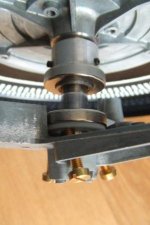
Triumph said:Picture of my mk2 version. Notice the three adjusting screws at the bottom and the alu ring with three screws on the top.
But still it fails. I think because of the great push and pull forces, short type bearing etc.
Thanks for pointing me to "supermagnet" more magnets available than in Germany.
I doubt your present design is ever going to work. If you can tilt the magnets or even move them laterally on the shaft using those brass screws, the ability to control parallelism between the magnets as the platter rotates is gone. You have to fix the magnets in position permantly and concentric with the axis of rotation. It is really simple if you think about it. Good luck.
'Triumph', I'm afraid that I completely agree with the comments made by 'Vinyl-addict'.
The problem is not because of the "great push and pull forces" as such, or because of the "short type bearing". The problem exists because the magnets are not truly parallel to each other and/or are not perpendicular to the bearing shaft. Your adjustment solution is cunning but is difficult (if not imposable) to adjust to a significantly fine degree. I'm afraid the problem has to be engineered out at a more fundamental level.
The problem is not because of the "great push and pull forces" as such, or because of the "short type bearing". The problem exists because the magnets are not truly parallel to each other and/or are not perpendicular to the bearing shaft. Your adjustment solution is cunning but is difficult (if not imposable) to adjust to a significantly fine degree. I'm afraid the problem has to be engineered out at a more fundamental level.
I think the problem is the stability of the tonearm. I've been racking my brain, trying to figure out how to do it......so far my brain isn't up to the challenge! LOLoshifis said:Could this excellent magnetic floating idea be applied to a DIY linear tracking tonearm? Smaller weigth, smaller (bar) magnets...
")
oshifis said:Could this excellent magnetic floating idea be applied to a DIY linear tracking tonearm? Smaller weigth, smaller (bar) magnets...
Unlikely. The application would fall foul of Earnshaw's theorem, which states that stable magnetic levitation with static magnets is not possible.
The thrust magnet schemes so far discussed get around this by using the bearing shaft as the mechanical "leash" element. This transfers the dynamic instability consequent to Earnshaw's theorem into rotational and especially precessional instability. I would be very interested to see whether anyone who has developed a completely floating magnetic bearing has actually measured these movements.
I can't see how you could achieve the same mechanical leashing with a linear tonearm. That doesn't mean it couldn't be done.
Mark Kelly said:
The thrust magnet schemes so far discussed get around this by using the bearing shaft as the mechanical "leash" element. This transfers the dynamic instability consequent to Earnshaw's theorem into rotational and especially precessional instability. I would be very interested to see whether anyone who has developed a completely floating magnetic bearing has actually measured these movements.
Hi Mark, I did measure "vertical" movement on the bearing I made. I mentioned it on the previous page.
Tonearm levitation
Could something like the drawing work? I'm envisioning the tonearm attached to a shortish angle-iron shaped magnetic structure which is trapped between two longer angle iron shped magnetic structures of opposing polarity. The two longer structures are embedded in a cylinder which is free to rotate in the vertical plane, allowing for warps and lifting the tonearm - or perhaps the tonearm could be hinged to its magnetic structure....
Seems that whichever axis the trapped structure tried to move along, it would be opposed by the outer structures - but perhaps this merely proves that I'm bad at thought experiments.
Regards.
Aengus
[Edit] Sorry, the image quality isn't great - by the time I'd converted to a .gif and then shrunk it, I lost a lot of detail. Luckily, my verbal explanation is impeccably clear.
Attachments
No, definitely won't work.
There is nothing to constrain the movement of the "floating" element except the magnets. Earnshaw's theorem says that they cannot achieve stable equilibrium so the system will move until some mechanical constraint is reached.
I would guess that the inner angle will tilt relative to the outer angle until the two lodge against each other but that's only a guess.
The problem briefly stated is this: a turntable platter only requires one degree of freedom, that of rotation around the Z axis. the sleeve bearing serves to constrain 4 of the other degrees (X and Y rotation and X and Y translation), leaving the magnetic bearing to constrain the last (Z translation). Since the disequilibrium forces from instability in the Z translation constraint will show up as X and Y translation and X and Y rotation (eg the platter will attempt to move sideways or rock) the sleeve bearing constrains them (adequately if it has really good tolerances, inadequately if not).
A tonearm however requires at least two degrees of freedom - If we assign the tracking direction as the X axis it requires translational freedom along this axis and rotational freedom about it. If a magnetic bearing is designed to supply the constraints on Z and Y translation then the instabilities again will show up in X translation and X rotation which are by definition not constrained. You therefore need a mechanical constraint which rather defeats the point.
Hi Mark
Thanks for the quick and lucid response; makes sense to me.
To highjack the thread momentarily - did you ever finish the DC motor control circuit boards (and/or complete controllers) you were going to market? I'm interested; please PM me if you have anything like this.
Regards.
Aengus
Thanks for the quick and lucid response; makes sense to me.
To highjack the thread momentarily - did you ever finish the DC motor control circuit boards (and/or complete controllers) you were going to market? I'm interested; please PM me if you have anything like this.
Regards.
Aengus
I have had a major detour into the area of multiphase AC motor drive design. I should be out of the woods in a month or two and will return to the DC design then.
I am confident I have worked out where I went wrong - I had an NFB loop enclosing a PFB loop and I couldn't satisfy the stability criteria. I'm now looking to use the PFB loop to accomplish a flat speed / torque characteristic and adding a very slow servo which only corrects for drift. This seems like a promising approach (and it's similar to what Teres has done).
I am confident I have worked out where I went wrong - I had an NFB loop enclosing a PFB loop and I couldn't satisfy the stability criteria. I'm now looking to use the PFB loop to accomplish a flat speed / torque characteristic and adding a very slow servo which only corrects for drift. This seems like a promising approach (and it's similar to what Teres has done).
Mark Kelly said:
Hope it works out, Mark. I'm still hoping for a DC design, though, since I've got a Maxon motor sitting on my desk making me feel guilty
Regards.
Aengus
This seems like a promising approach ...
Hope it works out, Mark. I'm still hoping for a DC design, though, since I've got a Maxon motor sitting on my desk making me feel guilty
Regards.
Aengus
Originally posted by Vinyl-Addict
I doubt your present design is ever going to work.
My construction is not going to work but I still am convinced that it is possible to make a simple but effective bearing with two relatively cheap ringmagnets. These neodymium magnets are very strong and it is my experience that it is not necessary to use big magnets. The magnets I used are 25 mm and more than strong enough to lift a steel platter.
A big difference between your designs and mine is that I use a existing TT as a base. But the main problem was that I did not build it accurate enough and adjusting does not solve this (the Mk1 version was fixed, but not accurate). It is not possible any more to make a new one because in the process I ruined the bearing.
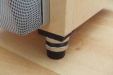
I let others do the experimenting my magnets are solved in a new project see picture below.
Guess what this is?
Attachments
I purchased some 5 mm dia 2 mm thick disc magnets from www.powermagnetshop.de in order to convert my Thorens TD160 Super into MagLev. I measured the pushing force between two disks facing the same pole towards each other, it gave about 150...300 g, depending on their distance. I used a digital kitchen scale for this, the magnets were in a tight fit tube and I pushed from the top with a pencil until they nearly touched. The weight of the platter is 3000 g, so I suppose 16 pairs will be sufficient.
My only problem is where to fix the magnets. The subchassis is made of steel, so it is not a problem on that. The platter (or rather the central element) has a plastic part that has a nice flat bottom surface that seems perfect diameter and width to fix the magnets. That plastic is like a cup or bell and its purpose is most probably keeping the oil from spilling around from the bearing.
But the flat surface of that plastic part is only at 1.5 mm distance from the subchassis, so there is no place for the magnets. So I came to the decision to remove the plastic, cut some from its height and refit. The only problem is that I could not remove that plastic part by hand by pulling/twisting and I did not want to force.
If someone has seen the inner platter and spindle assembly removed from the bearing sleeve, knows what I am talking about. Any idea how could I remove the plastic part, or increase that gap to 5...6 mm? There is a good picture at the bottom of this page:
http://www.theanalogdept.com/mk2clips.htm
Laszlo
As SQ states an element of cogging does exist if both sets of magnets are of the cylinder type. The solution is to use a ring magnet for one element. However, it is still important to construct this type of bearing to a high degree of accuracy. I believe that most of this was covered earlier in this thread. With regard to the Thoens; the first deck I ever modified was a TD160 and I remember the elements you mention. My solution was to remove the white nylon element altogether - I think I cut it off with a pair of clippers (it was 20 odd years ago so I'm not completely sure). I don't think it is fixed in any way other than being a very tight fit. Try twisting and pulling gently from the rear of the element rather than pulling on the flange. I would also remove the metal hook intended to locate with the flange. Neither of these elements is of much use in my view.
Thanks for all. I managed to remove the white plastic piece, it seems it has only transportation security purpose indeed. I tried one disc magnet on the chassis and several discs at the underside of the platter. It works and floats, but it does not float freely. The reason is the (over)damping effect of the air column in the bearing. The platter is still tightly coupled to the chassis through this air column and the friction (oil film) of the bearing.
- Status
- This old topic is closed. If you want to reopen this topic, contact a moderator using the "Report Post" button.
- Home
- Source & Line
- Analogue Source
- Magnetic turntable bearing