Hi all
Trying to adjust the antiskating force of my “SME 3009 II Improved” to suit the needs of my SHURE M97xE which is equipped with a brush damper, a few theoretical questions arose. Surfing around for answers three articles caught my attention:
1) B.B. BAUER: “Tracking Angle” (ELECTRONICS March 1945) [http://www.helices.org/auDio/turnTable/bauer.pdf]
2) J.K. STEVENSON: “Pickup Arm Design” (WIRELESS WORLD May-June 1966) [http://www.helices.org/auDio/turnTable/stevenson.pdf]
3) JOHN WRIGHT: “Bias Correction and Dynamic Conditions” , HI-FI NEWS October 1969
[archived at 09 March 2004 at www.Vinylengine.com]
In 1) Mr. Bauer provides the means to calculate the skating force across the arm’s travel, provided coefficient of stylus friction "mu" is known (he estimates a value of 1/3).
In 2) Mr. Stevenson estimates the lateral thrust (i.e. skating force) as 20% of downward pressure.
In 3) Mr. Wright explaining the results of his experiments, he comes to some conclusions, which seem to contradict Mr. Bauer theoretical calculations, like ” Bias force is therefore substantially unaffected by the surface speed” and “Bias force is therefore substantially unaffected by the playing radius”. The reason of the discrepancy is that these results (as also Fig. 5 and Fig. 6 of Mr. Wright article) are based on experiments conducted on unmodulated record grooves. At the end of his article Mr. Wright deals with modulated grooves and their effect on skating force. He concludes that “Bias force is therefore substantially directly proportional to modulation velocity-at least for sinewaves” . His Fig. 7 provides experimental data for friction coefficient ”mu” .
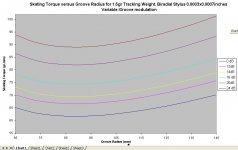
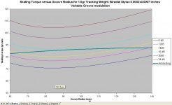
Combining formula from 1), and ”mu” data from 2) the attached drawing was produced. The 6 thin curves represent the skating torque produced when an elliptical 0.0003x0.0008in stylus hanged on a radial arm with the geometrical data of an “SME 3009 II Improved” is reading a record with grooves modulated with signal of varying modulation levels (0dB refers to 1cm/sec at 2 kHz).
Two things become easily evident:
a. The skating torque variation due to modulation variation is 30%.
b. The curves follow the form of the well-known tracking error curve.
Both smell trouble.
Practical antiskating mechanisms do not adapt automatically to increased skating torque due to varying groove modulation.
Practical antiskating mechanisms do not provide an antiskating torque, which follows such a curve.
(Continues)
George
Trying to adjust the antiskating force of my “SME 3009 II Improved” to suit the needs of my SHURE M97xE which is equipped with a brush damper, a few theoretical questions arose. Surfing around for answers three articles caught my attention:
1) B.B. BAUER: “Tracking Angle” (ELECTRONICS March 1945) [http://www.helices.org/auDio/turnTable/bauer.pdf]
2) J.K. STEVENSON: “Pickup Arm Design” (WIRELESS WORLD May-June 1966) [http://www.helices.org/auDio/turnTable/stevenson.pdf]
3) JOHN WRIGHT: “Bias Correction and Dynamic Conditions” , HI-FI NEWS October 1969
[archived at 09 March 2004 at www.Vinylengine.com]
In 1) Mr. Bauer provides the means to calculate the skating force across the arm’s travel, provided coefficient of stylus friction "mu" is known (he estimates a value of 1/3).
In 2) Mr. Stevenson estimates the lateral thrust (i.e. skating force) as 20% of downward pressure.
In 3) Mr. Wright explaining the results of his experiments, he comes to some conclusions, which seem to contradict Mr. Bauer theoretical calculations, like ” Bias force is therefore substantially unaffected by the surface speed” and “Bias force is therefore substantially unaffected by the playing radius”. The reason of the discrepancy is that these results (as also Fig. 5 and Fig. 6 of Mr. Wright article) are based on experiments conducted on unmodulated record grooves. At the end of his article Mr. Wright deals with modulated grooves and their effect on skating force. He concludes that “Bias force is therefore substantially directly proportional to modulation velocity-at least for sinewaves” . His Fig. 7 provides experimental data for friction coefficient ”mu” .
Combining formula from 1), and ”mu” data from 2) the attached drawing was produced. The 6 thin curves represent the skating torque produced when an elliptical 0.0003x0.0008in stylus hanged on a radial arm with the geometrical data of an “SME 3009 II Improved” is reading a record with grooves modulated with signal of varying modulation levels (0dB refers to 1cm/sec at 2 kHz).
Two things become easily evident:
a. The skating torque variation due to modulation variation is 30%.
b. The curves follow the form of the well-known tracking error curve.
Both smell trouble.
Practical antiskating mechanisms do not adapt automatically to increased skating torque due to varying groove modulation.
Practical antiskating mechanisms do not provide an antiskating torque, which follows such a curve.
(Continues)
George
Attachments
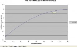
I measured the antiskating arm length and the antiskating weight of my “SME 3009 II Improved” (arm 22.225mm/hanging weight 2.75gr). I did some calculation and a diagram of antiskating torque versus groove radius for 1.5gr tracking weight was produced (see attachment).
(Continues)
George
(Continues)
George
Attachments
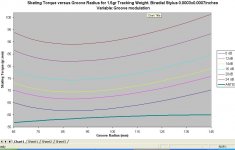
Combining the two diagrams in one the following attached diagram is produced.
The antiskating torque of SME arm is shown by the thick green curve. It shows that antiskating mechanism under-compensates the theoretically calculated skating torque produced by an elliptical stylus 0.0003x0.0008 inches.
(Continues)
George
The antiskating torque of SME arm is shown by the thick green curve. It shows that antiskating mechanism under-compensates the theoretically calculated skating torque produced by an elliptical stylus 0.0003x0.0008 inches.
(Continues)
George
Attachments
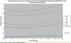
This under-compensation becomes more severe when in the theoretical calculation of skating torque, man plugs in the friction coefficient for a stylus 0.0002x0.0007inches as is the case for my SHURE M97xE. The attached diagram shows this.
(Continues)
George
(Continues)
George
Attachments
The intend for opening this thread is to discuss the subject of skating calculation and to ask the members of the forum if they have observed signs of skating under-compensation with their radial arms similar to these that my calculations show.
Attached you will find the spreadsheet I prepared with the various calculation sections. Light blue shells are look-up table data. Light green shells with black letters contain data used for calculations. Light green shells with red numbers are your input data. Light brown shells are calculation result data. Spreadsheet is not locked, so keep a copy before start inputting data.
Regards
George
Attachments
antiskate
Hi, very interesting figures. From a practical pov. I don't seem to come to systematic conclusions re antiskate. Tendentially on unipivots like the Hadcock 242 I don't use it, as the sonic degradation is audible. On a Mission 777 less so. I use it on a Schroeder DPS as it is very accurate.
However I believe that most records are manufactured with a slight dip towards the central section. This means that pressure will be greater towards the inner groove for the first half of the lp, and on the outer groove at the end. This is rarely audible in my system. However with a linear air bearing and a Koetsu (stiff suspension cartridge), it can be at times.
I have used a couple of grooveless records and both the Schroeder and my Linear air bearing i've found that the antiskate will only fix the arm in certain points on the record. This again is probably due to minute variations in the disks themselves, but that will be the case with grooved records. In the end, I find I set antiskate by ear, occasionally using the Hifinews tracks.
gpagag: Your investigations are interesting but I think it would be a good idea to set your graphs so that they plot from zero and reach the same "Y" axis limit in each case. I think it's also a good idea to bear in mind that the coefficient of friction between materials is for polished flat surfaces. There's a lot more going on when a lump of diamond rattles around in a vinyl groove.
However, bias (I far prefer that term to "anti-skating") is an important factor in radial arm design. I use a unipivot of my own design and put considerable effort into ensuring that the application of bias force didn't upset arm geometry. It's not easy, and bias is always a compromise. Have you considered the effect of groove modulation on bias? I will try your speadsheet (always assuming that Lotus123 can cope with it).
ebarker: I sacrificed a Carpenters LP to science by sawing it diametrically in half and measuring thickness at various points. Some LPs are observably flat, but the one I chose was not. I don't seem to have the numbers to hand, but the slope was very gradual and I posted numbers on this forum.
ebarker wrote:
EC8010 wrote:
This is a topic which I think is given attention inversely proportional to it's importance. Mr. John Wright (ref. 3 of post #1)makes it clear from the beginning. It is also clear that "mu" values derived from Fig.7 do contain the results of what happens "when a lump of diamond rattles around in a vinyl groove". If it wasn't, "Friction vs. Modulation" Curve would be a straight line parallel to X axis. These are the "mu" values that I have used in the look-up tables of the speadsheet. So to answer your question. Yes I have considered the effect of groove modulation on bias. Consideration is not enough though. It has to be backed -up by supporting data. And this I don't have other than the three references I quoted. Please contribute to the subject by supplying or linking to such data and expressing your opinion. It won't hart if I will be proven wrong. The tittle I chose for this thread is a humorous way of showing my uncertainty to the topic.
That said, from what I know so far, I would say that the theoretical analysis of Mr. Bauer is correct. The data of Mr. Wright are the only that I could find and are pointing to the right direction. There are a few points in his article though that are a bit loose in their expression (not clear if he is referring to modulated or unmodulated grooves), so I am not certain if he has taken everything into account. I think he has not considered the increase in modulation velocity going from outer groove to inner groove. I would like your opinion on that and how can such a variable be coded for to be imported into an equation.
EC8010 I would like to ask you on what grounds did you design the bias system on your arm?
Regards
George
Your note that antiskating mechanism (presumably adjusted according to manufacturer's instructions) on each one of these arms gives different audible results, is an indication that something is not clear about antiskating; either arm manufacturers have designed their antiskating mechanisms empirically (i.e. with no established rule on which the antiskating torque would adhere to), or they have ill implemented an established theoreticall model. I tend to believe that the former is true.From a practical pov. I don't seem to come to systematic conclusions re antiskate. Tendentially on unipivots like the Hadcock 242 I don't use it, as the sonic degradation is audible. On a Mission 777 less so. I use it on a Schroeder DPS as it is very accurate
In the applicable standard which you can find it here http://www.aardvarkmastering.com/riaa.htm , fig. 1 shows the cross section of a "should be" 12inches record. The slight dip is toward the outer section. It seems that they adopted this cross section for to protect (the grooved part of) the record from wear when records were stacked and thrown down on each other with the automatic multi-disks record players of that time.[However I believe that most records are manufactured with a slight dip towards the central section.]
Can you please check and report if these "certain points" coincide with the null tracking error points?I have used a couple of grooveless records and both the Schroeder and my Linear air bearing i've found that the antiskate will only fix the arm in certain points on the record.
EC8010 wrote:
I did it on purpose for level and curve contour differences to be enlarged (zooming-in at these .jpeg drawings is not a good option due to imposed file size limit). In any case, Y scale numbering is clearly visibleI think it would be a good idea to set your graphs so that they plot from zero and reach the same "Y" axis limit in each case.
I couldn't agree more.I think it's also a good idea to bear in mind that the coefficient of friction between materials is for polished flat surfaces. There's a lot more going on when a lump of diamond rattles around in a vinyl groove.
This is a topic which I think is given attention inversely proportional to it's importance. Mr. John Wright (ref. 3 of post #1)makes it clear from the beginning. It is also clear that "mu" values derived from Fig.7 do contain the results of what happens "when a lump of diamond rattles around in a vinyl groove". If it wasn't, "Friction vs. Modulation" Curve would be a straight line parallel to X axis. These are the "mu" values that I have used in the look-up tables of the speadsheet. So to answer your question. Yes I have considered the effect of groove modulation on bias. Consideration is not enough though. It has to be backed -up by supporting data. And this I don't have other than the three references I quoted. Please contribute to the subject by supplying or linking to such data and expressing your opinion. It won't hart if I will be proven wrong. The tittle I chose for this thread is a humorous way of showing my uncertainty to the topic.
That said, from what I know so far, I would say that the theoretical analysis of Mr. Bauer is correct. The data of Mr. Wright are the only that I could find and are pointing to the right direction. There are a few points in his article though that are a bit loose in their expression (not clear if he is referring to modulated or unmodulated grooves), so I am not certain if he has taken everything into account. I think he has not considered the increase in modulation velocity going from outer groove to inner groove. I would like your opinion on that and how can such a variable be coded for to be imported into an equation.
EC8010 I would like to ask you on what grounds did you design the bias system on your arm?
Regards
George
gpapag: I fixed your link to Vinylengine, but I couldn't seem to find the John Wright article. Your link to the RIAA standards doesn't work, but I don't understand why. When I searched for Aardvark mastering, I found the RIAA standard and it had the address you used. Odd.
As for my bias design, the main requirement was that it should work without upsetting the unipivot. As has correctly been said earlier in this thread, it's easy to upset a unipivot with off-centre forces. My arrangement applies the force at the pivot height to avoid this problem. I used constant bias force because I had no evidence at the time (fourteen years ago) that anything else would be better. There's no reason why my design couldn't be adapted to produce a nonlinear force simply by fitting an eccentric sleeve around the existing arm pulley. I suspect the outer surface would have to be cut by hand, but it wouldn't be too difficult.
As for my bias design, the main requirement was that it should work without upsetting the unipivot. As has correctly been said earlier in this thread, it's easy to upset a unipivot with off-centre forces. My arrangement applies the force at the pivot height to avoid this problem. I used constant bias force because I had no evidence at the time (fourteen years ago) that anything else would be better. There's no reason why my design couldn't be adapted to produce a nonlinear force simply by fitting an eccentric sleeve around the existing arm pulley. I suspect the outer surface would have to be cut by hand, but it wouldn't be too difficult.
Bias
Gpagag,
The aardvark site shows a diagram that confirms what i find with a lot of records
http://www.aardvarkmastering.com/riaa-1.gif
that is a dip towards the centre. You might be familiar with Stan Rickers interview at Cardas Audio
http://www.cardas.com/content.php?a...stering,+an+interview+with+Stan+Ricker+Part+I
He talks about records there being made in a kind of U shape for stacking purposes.
the problem with of using grooveless records to gain information is of course that they bear no real relationship to real grooved records. Its practically impossible to decide whether the different forces at work on a grooveless record originate from the vinyl, other centrifugal forces, or from the arm. Using a grooved 'run-in'record like the clearaudio is pretty useless as well, because its mastered not to produce sound or calibrate real life bias.
The problem with bias is that the complex dynamic forces operating on the stylus vary. The bowl shape or dip in the record has different shape with each record, and if the record is also eccentric, will be all the more complex to calculate. Its no suprise to me that Harry Weisfield of VPI removed antiskating from one of his arms completely. In my experience some cartridges are much more 'bias' sensitive than others. A good tracker with relatively high compliance can usually get by with much less bias than others. I also find that needing to use more bias can be a sign that the cartridge needs retipping.
best
edward
'I sacrificed a Carpenters LP to science by sawing it diametrically in half and measuring thickness at various points. Some LPs are observably flat, but the one I chose was not. I don't seem to have the numbers to hand, but the slope was very gradual and I posted numbers on this forum.'
Its always the Carpenters who get sacrificed . The bias issue only really gets critical imo when either the cart mistracks, or its audibly favouring a groove, or if there's long term wear to one side, pushing the cantilever over. Air bearings are i guess the most likely to mistrack, because they are so level, and their lateral mass changes at the point where the dip changes. Some people prefer to align their air bearings out of level for this reason. That's also true for the Clearaudio/Souther. In practice this can make for even greater problems if the record is eccentric (and to some extent it usually is).
Its always the Carpenters who get sacrificed
. The bias issue only really gets critical imo when either the cart mistracks, or its audibly favouring a groove, or if there's long term wear to one side, pushing the cantilever over. Air bearings are i guess the most likely to mistrack, because they are so level, and their lateral mass changes at the point where the dip changes. Some people prefer to align their air bearings out of level for this reason. That's also true for the Clearaudio/Souther. In practice this can make for even greater problems if the record is eccentric (and to some extent it usually is).Dear all
Trying to find data about modulation velocity changes versus groove radius, i fell over this sitehttp://www7a.biglobe.ne.jp/~yosh/sitemap.htm
I just went through the titles.
It seems like the puthhy cat has already been under a japanese microscope. I have quite a lot work to do ( i mean work), so i don't find it prudent to withhold such wealth of information not for a moment.
Enjoy.
I will be back in a few days with comments
P.S. It seems that John Wright's article has dissapeared from VinylEngine site. Nevertheless, i have it in my hard disk. It is ~500kB. I would e-mail it to anyone interested. By the way, if someone has the second part of this article in his possession, i would be very interested to have a copy
Regards
George
Sorry for kicking this old dog.In 2) Mr. Stevenson estimates the lateral thrust (i.e. skating force) as 20% of downward pressure.
BUT, is it possible to make approximations of skating force as a percentage of VTF at various levels of modulation, in accordance with Mr. Wright's findings?
That is, does Mr. Stevenson's 20% become something more like 30% under rather extreme modulation?
Is it possible to find Mr. Wright's article somewhere? I looked at vinylengine.com but they seem to have manuals but I can't find articles.
Thanks in advance for any help.
- Status
- This old topic is closed. If you want to reopen this topic, contact a moderator using the "Report Post" button.
- Home
- Source & Line
- Analogue Source
- A think a thhow a puthhy cat