Harms RIAA
Hi,
I could easily find Harms' version of ACCURATE formulae for the RIAA filters.
This is for the playback curve before the newer IEC with rolled off bass and it does not include the Neuman 50kHz adjustment.
As with all filters these calcs assume zero source and infinite load impedances.
I have another spreadsheet that converts RIAA time constants to response values. It would allow comparison of response errors due to finite in/out impedances and thence corrections to the filters. But I'm sure someone out there has a simpler method.
Attachments
leadbelly said:
Well, I am still confused, since you refer to a 52K resistor, but in richie00boy's schematic we see a 68K resistor combined with the 1.5K.
Yes, I was intrigued by this as well. I'm using the schematic published in "Self on Audio". I don't have a copy of the original magazine articles at home, but will look them up when I get back to work.
As I said before, I spoke directly to D Self about this, and he confirmed that the sum of R22 and R23 should be 53.5K - what more can I say? Feel free to email him yourself if you want to be doubly sure
")
Just to show you the problem I faced, I've scanned in a section of the schematic from the book. As you can see, it's pretty hard to read, which is why I originally approached the author.
Attachments
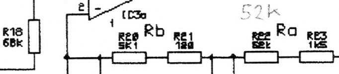
The "pixelisation" is present on the page - it's not caused by my scanner. It's almost impossible to guess at a value for R22, but note that R18 is 68K, and that the value for R22 looks nothing like it.
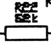
I scanned at 1200dpi in an attempt to show the problem. But of course the above image was downsampled to make it fit here. So here's a full resolution close-up of R22 - not sure it helps!
I scanned at 1200dpi in an attempt to show the problem. But of course the above image was downsampled to make it fit here. So here's a full resolution close-up of R22 - not sure it helps!
Attachments
richie00boy said:Well I can vouch that what I posted is what is in the magazine. Whether Doug then changed his design slightly when publishing in the book (which came along a good few months, maybe a year or so, later) is the only guess I can come up with.
Yes indeed - that was my best guess also. For info, the book was published 4 years later in 2000. And IIRC, it was 2002 when I had the email conversation with him.
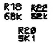
For kicks, I went back to the original scan and put the text for R22 next to the text for R18 (68K) and R20 (5K1). Looking at the "6", I don't think R22 could be mistaken for 62K - the left hand edge is much more rounded. Compare it to the "5" of R20.
Incidentally, if anyone is considering building this, please note that the output is a bit on the low side as the Precision Preamp was designed with a nominal line input level of 200mV. It really needs another 10-20dB of gain to make it match better with other source components. I effectively "fix" this in software in my preamp, but did ask Douglas about modifying the RIAA preamp for more gain, but he politely declined (understandibly - it's not a trivial exercise!) If I was building it again, I'd add another op-amp after the IEC filter. Or consider removing the IEC filter function from the second op-amp and using that to provide the gain...
Not a big deal, just thought you'd like to be aware...
Cheers,
Mark
Attachments
I finally located the Reg Williamson article on the RIAA equalization. The attachment has the 4 RIAA networks with the correct time constants. In all cases R2 mainly determines the 1 kHz gain. When you select R2 you are implicitly selecting all values because R1 and R2 have a fixed ratio.
Hope this helps.
Regards,
Ray
Hope this helps.
Regards,
Ray
Attachments
Hi all,
comparing the Harms' to Williamson for two circuits ( b & d) I see that Harms' values are identical to 4 significant figures, only the fifth sig. fig. varies. It looks like Harms may have used Williamson's paper for his article.
The spreadsheet will give you accurate R&C values for the two comparable circuits.
Can anyone see if Williamson's a & c circuits are equivalent to the two Harms' circuit on the left in the diagrams or are they a completely different case? Note that c & d have the same R1/R2 ratio = 6.8773
EC8010 said:I expect they all came from the Lipshitz paper which doesn't give values but gives the formulae into which to drop the required time constants.
Don't people work from first principals anymore?

If you fancy doing the complex algebra as a mental exercise, then feel free. I calculated the response of an inverse RIAA network from first principles and had to align my paper to landscape, and I only did it because it was absolutely necessary. Why trudge through repeating Lipshitz? The reason it was publishable was that it represented a great deal of work.
PS We hope that school principals have principles.
PS We hope that school principals have principles.
Off topic of RIAA networks.
The algebra is very simple if you use a symbolic algebra program such as DERIVE. It is available for a 30 day free trial at http://www.derive-europe.com/main.asp .
I have a DOS version of the program from the early 1990s that came on a single 3.5" diskett. It did an amazing amount of algebra and calculus. I used the program recently to calculate some derivatives and it ran perfectly fine in a DOS window on a 1gHz Pentium. The answer would pop up as soon as you hit enter. No need for pencil and paper.
Regards,
Ray
- Status
- This old topic is closed. If you want to reopen this topic, contact a moderator using the "Report Post" button.
- Home
- Source & Line
- Analogue Source
- Will the correct Doug Self Wireless World RIAA please stand up?