Close, but you have the wrong way around. The amount of antiskate required increases as the needle moves towards the inside (AFAIK!).
Your system could work, but I wonder about reliability, cup drying out, seive getting blocked etc etc etc. Even though I don't own an arm with it, the magnetic solution has to be the most elegant.
The old weight on a string is good enough for many high end designs, so I wouldn't dismiss it out of hand.
Fran
jamikl got it right, tracking force decreases closer to the spindle. The radius is smaller and the surface speed is slower. Carlo Morsiani has done extensive testing for his unipivot tonearm that uses magnets for anti-skate, he states tracking force decreases as the stylus moves closer to the spindle.
forgive if...
this material has been mentioned as I have not read the entire thread. Pitsburg Corning make an interestin material for cryo insulation, glass foam. This material is very light and rigid. It is easily worked but do not breath the dust as it is toxic as well as being glass powder. I would think that if an arm were fashioned with this foam it could then be dip coated with a layer or two of laquer to damp out any risidual structural resonances. I have wokrd with samples of this material and can say it is strong rigid light and is super easy to form (you can form it with a pocket knife blade as well as machine holes etc.) and it is easy to bond to as it is glass and porus by nature. Check it out. I imagine it to be the ideal arm material.
http://www.foamglasinsulation.com/about_foamglas.asp
We are talking about two different but related things. Antiskate is created by the mechanism that is added to the tonearm (string weight, magnets, spring etc). The antiskate force is user created and generally remains constant across the record.
The lateral or side force of the grooves on the stylus is the reason for the antiskate mechanism. The force created by the grooves on the stylus is weakest toward the center of the record. Carlo Morsiani uses magnets for his antiskate mechanism, he has found a way to create antiskate force that is variable and gets weaker as the stylus nears the center of the record.
So, conventional antiskate mechanisms generally create a constant antiskate force across the record.
The grooves on the record create a force that changes getting weaker as the stylus moves toward the center.
Carlo explains it here, this is a great read for tonearm builders. He uses a gramophone needle for the pivot, very clever. I have 99 left from my order.
http://www.morsiani.it/cm1.htm
Fran, my previous post I used the term tracking force, this is generally used to describe the weight on the stylus, I think I added the fog.
humble antiskating idea
Hi all. Very interesting thread.
I´m currently in the process of making an arm base for a Technics epa-501 armwand that some friend gave me (only the complete wand, without the base, bearings, antiskating device etc)
The wand is a very interesting one -albeit very low mass-, made from titanium nitride.
I was thinking about using the common thread and weight antiskating scheme, but substituting the little weight with some ¨pending magnet¨ -a very little one, taken from the broken optical frame of a dead cd player- (by the way, if your pulse is steady, lenses of dead cd players are very powerful loupes to check styli).
Below the pending magnet, with enough clearance provided, another reversed magnet -or a piece of iron-, acting as ¨attractor¨, provides the torque needed for biasing the arm/stylus.
Note: the magnet needs to be a very little one, because it´s weight adds (in this scheme) to the bias force provided by it´s intrinsic magnetic force. A weighty magnet cannot be adjusted in the proper way to perform the task described here!
Varying the lenght of the thread establishes the amount of bias needed in, for example (and as a way to set some initial bias value) , the outer part of the vinyl disc.
There, skating forces are at a peak.
Digression: I use, for this experiments, a dummy, grooveless vinyl test record made by Telefunken in the sixties.
With no bias at all, in this outer part of the record, a very noticeable acceleration of stylus towards the centre of the disc is clearly discernible. That acceleration decreases drastically when the stylus approachs inner zone.
Inertia keeps the tonearm in motion towards the spindle,though. But if the stylus is placed directly in the inner zone of the disc, it barely moves toward spindle at all)
Back to the magnet scheme: As the stylus gets to the middle of the disc, the amount of bias decreases -because the tiny magnet has moved away a little from it´s attractor-
And when the stylus reaches the inner zone of the disc, the distance between magnet and attractor is at maximum, so bias forces tend to be not so drastic as in the outer zone of the disc.
I know that Mr. Morsiani has created something that, if I understood well, works on a similar principle.
But maybe this ´pending magnet¨ scheme is more suitable for diyers in a hurry.
I have been doin´ some raw experiments, and the results looked promising. Difficult to setup properly, but promising.
Just an idea.
Cheers!
well...
As I said earlier, I was trying to put togheter a Technics epa501h armwand (eighties vintage, low mass, dynamic damping) and make it sing.
It´s very difficult to make a gimbal -the design of this nice arm does not allows unipivot mounting-...
All the experiments were done with recycled or reused material, scrap from test equipment, dead electronic parts etc.
No animals were harmed in the experiment...
But too much profane words was spelled, believe me!
Initially I used some little ball races for the vertical movement, but the results were no so stellar (bearing chatter, IMO): ultra low friction -putting some 1cm2 piece of paper upon headshell (some 10 mg) made it react in visible form), but some mistrackin...
I tried to give more mass to the armtube, but with no effect.
And the ball races tended to loose alignment...
Finally, I opted for some form of ¨composite gimbal¨ : ball races for the horizontal movement, and point/cup assemblage for the vertical movement: downpoint biro points mounted in threaded bars (for easily adjustable azimuth), resting in jewel cups...
Now, the problems: mistracking persists with a variety of medium to low compliance MM carts (shure v15, shure m70, some audiotechnicas)...
I altered the tube mass with some very difficult to do mahogany wrap (cyanoacrylate and lots of patience and sticked fingers...)
The mahogany covered arm looks beautiful, and it´s mass was increased in some 4/5 grams, so a better match with less compliant carts. Better tracking, but not on par with a SME3009 still...
I´m suspecting about the plane on which the vertical motion of tonearm rests. I have read somewhere that a coincidence between stylus and pivot point (the two in the same horizontal plane) is desireable... But that scheme doesn´t works well in this case...
Does any of you know if a coincidence between armtube axis and vertical movement axis is convenient (this in a gimballed tonearm)? I have seen such a thing in some common tonearms as standard. But some other manufacturers claim for bearings mounted below the plane of the armtube...
Thanks in advance
Attachments
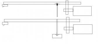
If you look at your two diagrams it is not ouright stability that is the major issue but more an issue of changing geometry.
If you consider the lower diagram; as the cartridgre tracks warps the arm will move around a pivot with a radius the length of the supporting bearing - this will wildly alter the relationship between the stylus and the groove.
The effect is much smaller in the top diagram because the distance (in the horizontal plane)) between the Stylus and the pivot point is much smalller.
Ideally, the centre line of the mass of the counterweight should be in the same horizontal plane as the tip of the stylus to reduce the effect of tracking weight altering when warps are tracked.
If you look at a Ladegaard arm, the pivot point is more like the lower of Nanook's 2 drawings. However, the pivot point, and the stylus are at the same height. The centre of mass of the counterwieght is below both of these.
I have made a tonearm with vertical bearings something like the Ladegaard desigh, but with the bearing head from a VHS machine as the horizontal bearing. The vertical bearing is made of a knife blade resting on 2 edges of Ali on the head drum.
The 'Headshell' is a peice of metal on the bottom of the arm tube, just big enough to provide a flat surface to mount the cart on. In this way, the record surface, pivot pint and counterwight are level.
When the counterweight was above the pivot point, the VTF would vary wildly- if the arm was up high, it would stay there, and if it was low, the VTF was very high (IIRC- could be the other way round). With the C.O.M. of the weight level with the pivot, the VTF was far more stable. I have not tried with the C.O.M. below the pivot point.
james
All the reading I've done, and I've done a lot over the past few days - including patents, indicates that the stylus tip, the pivot point, the counterweight should be in a straight line although it seems that centre of gravity may be allowed to be partly below this line but not far enough to create any pendulum effect which the 2nd drawing certainly would.
When viewed from the front the stylus - cartridge assembley has a slight tilt or lean - is this usually arranged at the headshell or with a shim under the cartridge or where?
jamikl
When viewed from the front the stylus - cartridge assembley has a slight tilt or lean - is this usually arranged at the headshell or with a shim under the cartridge or where?
jamikl
That sounds about right.
Re the lean: Do you mean a front-rear lean (Vertical Tracking angle) or a side-to-side lean (Azimuth)? VTA, if adjustable, is usually adjustable by raising or lowering the mount of the tonearm. Azimuth is done wither with thin shims under one of the cartridge screws, or by twisting the headshell- if possible.
james
yes, Nanook, sounds strange...
and apparently introduces some form of assimetry that leds me to think (maybe wrongly) that the tonearm lever effect is somewhat distorted...
But not so out of the blue if I´m understand well what I can see of the Wheaton Triplanar ( http://www.triplanar.com/), where the armtube is partitioned in such a way so record surface and bearings are at same level...
But, yes, in that example pivot point and center of gravity (weight) are at same level.
That´s a very complex one example, and has very little in common with this experiment of mine.
I was doin´some adjustments and listening since my last posting.
Thank you very much for all the advice provided meanwhile!
(Nanook, Ynwoan, Jrewillug, Jamikl et al)
In the scheme that I have adopted, putting bearings at record level only causes severe mistracking, loss of bass and ¨hollowness¨ in the sound.
I understand now that this happens because center of gravity is too high.
And all those nasty things dissapeared when arm longitudinal axis and vertical movement (bearings) axis intersect each other (as in a ¨cross¨ figure) .
Now the cart/arm combo tracks extremely well -in fact, the cheap and old Shure m70 -spherical stylus- that i´m using for this experiment is sounding like a much more sophisticated cart/stylus!-
TNWoan...and others
re: changing geometry, YES. But also controlling a "hung" mass is easier than a "sprung" mass. Same holds true regarding using bearings. Try controlling an arm such as the 2nd one in my sketch vs the 1st one.
re: centreline of the counterweight mass in"line" with stylus tip--YES, or slightly below.
The counterweight can be below.
Implementing a unipivot is much much easier, as is the azimuth adjustment, when an anit-skating device is used.
- Status
- This old topic is closed. If you want to reopen this topic, contact a moderator using the "Report Post" button.
- Home
- Source & Line
- Analogue Source
- making a tonearm...