Hi Sheldon,
You may end up being correct, BUT, its's not just the silicon holding the pressure. At the top, other than a 1/8" wide silicon bead a 1/2" deep, its sealed with a 1/4" copper disc. At the bottom, other than a thin layer of silicon sanwitched between the foot plate and the plinth, a 1/2" thick piece of arcylic ( Corian) is sealing it. The walls of the pod cavities are a 1/8" layer of silicon over laminated Corian and metal.
I am not saying the pressure won't diffuse...eventually. I do believe however it will take a l-o-n-g time. Exactly how long remains to be seen (I haven't found any studies regarding bubble-wrap pneumatic springs). If I understand the physics (and I am not at all sure that I do), their needs to be a pressure differential in order for diffusion to take place. The pressure in the bubble-wrap is being equalized by the pressure of the silicon pushing back. The pressure of the silicon is being equalized by the Corian pushing back. To hedge my bet, I plan on coating the silicon in a layer of Plasti-Dip rubber before final assembly.
The patter & top plenth together weigh approx. 45 lbs.. The discs have around 5 sq. ins. of surface area each, for a total of 15 sq. in.. If the weight was distributed equally, that would be 3 psi. of pressure. I'm guessing the distribution is more like 4 psi. on the front feet and 2 psi. on the back foot. I don't think this will contribute greatly to diffusion.
From Sheldon,
From maxro (hello)
These suggestions go under the heading of "Plan B". If I turn out I am full of it regarding the pods longevity, I will plumb it. In fact, this was my first plan. It was while I was laying out how best to do this that I saw the bubble stuff laying in the corner.
Casey
Not as long as you might think. Air slowly diffuses out of tires (or tyres) and your construct has a much higher surface to volume ratio. Also, silicone sealant has a particularly high permeability (diffusion rate x gas solubility). You could lift the unit off the feet when you are not using it to maintain the air volume in your pads.
You may end up being correct, BUT, its's not just the silicon holding the pressure. At the top, other than a 1/8" wide silicon bead a 1/2" deep, its sealed with a 1/4" copper disc. At the bottom, other than a thin layer of silicon sanwitched between the foot plate and the plinth, a 1/2" thick piece of arcylic ( Corian) is sealing it. The walls of the pod cavities are a 1/8" layer of silicon over laminated Corian and metal.
I am not saying the pressure won't diffuse...eventually. I do believe however it will take a l-o-n-g time. Exactly how long remains to be seen (I haven't found any studies regarding bubble-wrap pneumatic springs). If I understand the physics (and I am not at all sure that I do), their needs to be a pressure differential in order for diffusion to take place. The pressure in the bubble-wrap is being equalized by the pressure of the silicon pushing back. The pressure of the silicon is being equalized by the Corian pushing back. To hedge my bet, I plan on coating the silicon in a layer of Plasti-Dip rubber before final assembly.
The patter & top plenth together weigh approx. 45 lbs.. The discs have around 5 sq. ins. of surface area each, for a total of 15 sq. in.. If the weight was distributed equally, that would be 3 psi. of pressure. I'm guessing the distribution is more like 4 psi. on the front feet and 2 psi. on the back foot. I don't think this will contribute greatly to diffusion.
From Sheldon,
edit: or you could tap a hole into the gas chamber and fit an airtight screw. When your pads flatten too much, you can lift the table and open the screw to let a new charge in.
From maxro (hello)
Or, you could glue in some valves from old bicycle inner tubes and inflate them with a very low volume pump, such as that used for mountain bike supension forks.
These suggestions go under the heading of "Plan B". If I turn out I am full of it regarding the pods longevity, I will plumb it. In fact, this was my first plan. It was while I was laying out how best to do this that I saw the bubble stuff laying in the corner.
Casey
First things first.
HFGuy and Sheldon…Mea Culpa, Mea Culpa Mea-Maxima Culpa…bubble wrap was one of my less stellar ideas. You guys were right on with the diffusion problem…in retrospect, I think I was trying to “will” it to work. I will get back to the suspension later ( hint: I have acquired a 12V compressor, some small pneumatic solenoid valves , and a pressure sensor IC), but right now , I’ve been working on speed control.
My first task was to reduce the radius of the platter about .025” with the sanding drum made for the job. While profiling the plinths, I managed to undersize them slightly, causing the edge of platter to overhang. Once this was corrected I moved on to the strobe pattern.
My PSN (Platter Speed Neurosis) dictates that I must be able confirm speed at any time…a permanent strobe pattern is in order. In the “real” manufacturing world, a few lines of G-code fed into a 4 axis CNC mill would whip out a pattern in a couple of minutes. My world has a lathe and a modified drill press.
I spent the first day cobbling together a “dividing head”…
…actually this is the fourth revision. Originally the shaft was a piece of wood dowling...didn’t work out. Then the collar on the dividing wheel cracked, causing the spacing to shift…it was then glued. Then the set screw in the collar holding the platter to the shaft vibrated loose, causing the spacing to shift…it was glued. After each failed attempt, holes were filled, and drilling became harder.
Spacing was set by printing a pattern drawn with AutoCad, cutting it into strips, and taping end to end…
…if your incredibly lucky, the last piece will land on the line…I wasn’t. Getting it right entails shifting the “print scale” in .01% increments up and down until it does. Once I got the pattern to line up, I drilled a hole .04” deep after each graduation is lined up…
…and the break is set…
…this process is repeated for each hole (actually multiple times for some holes due to the failures). I intend to fill the holes with reflective paint on the final finish, but for now I painted the bottom of the platter white, then blackened it with a Sharpie felt pen for contrast…
Using the shop florescent lights as a “strobe” confirmed that sanding a profile on the drive pulley lowered the speed slightly. Not to worry, The speed control would fix it.
I was trying to decide which approach to take for signal generation for the AC supply when I ran across the Maxim MAX29x series of switched capacitor filter. This slick chip is a 8-pole low pass filter with the corner frequency determined by its clock frequency. You feed it a clock 100X the corner frequency, 6000 Hz for a corner of 60Hz for example. By feeding it a square wave of the desired frequency, you get a low distortion sine wave of stable amplitude. It also has a built in op amp that can be set up for an additional 2-poles of filtering.
Here is the basic logic configuration feeding it, it is an early draft and doesn’t show the op amp filter…
A signal source 400X the desired frequency (more on that in a bit) feeds both a 4013 flip-flop, and U2, a 4017 decade counter. The 4013 is configured as a divide-by-4 providing the 100X clock for the filter. U2 is set up as a divide-by-ten, and feeds U3 set up as a divide-by-5. This composite divide-by-50 pair provides a clock 8X the target frequency. Up to this point could have been simplified if all I wanted was one signal…but I want a two phase supply with a 90 deg. shift between them to drive a synchronous AC motor without a run capacitor. I needed the 8X for this part, the final 4017 is set up as a divide-by-4. Since each of the four outputs are high 25% of the time..in other words 90 deg. apart…all I need to do to get my 2 phases, is to take the signal from 2 neighboring outputs. I now have 2 clocks 2X times the target. These feed a final flip-flop to get my final frequency into the MAX291, and two clean sine waves 90 deg. apart are ready to feed the power amp. Besides eliminating the need for different run caps for the different speeds, the “cleaning” effect of the dividers means that the only thing you have to worry about with the oscillator is frequency stability. Wave shape , distortion etc. doesn’t matter. This broadens the oscillator options significantly.
For my oscillator, I’m using a Advanced Linear Devices ALD555 set up as a astable multivibrator. The ALD555 only needs one resistor and one capacitor for this, making changing the frequency easy.
For the strobe, I built The Vinyl Engine's strobe circuit (is this the same as dice45’s?). The construction is perfboard and hot glue point-to-point…
…Everything to the right of the reed relays is the divider/filter block. The wiring was very simple up to the 2-pole analog filter built around the MAX291 op amp…it got pretty “busy” there. In the middle is the oscillator, the relays pull in different values of timing resistors, changing the speed. Not seen is the trim pots on the end of the pigtail plugged in below the relays. The little circuit to the left is the strobe.
I played around with a couple of options for the power amp before settling on the TA8215 , a 18W Chn. BTL amp designed for car stereos. I built the amp straight out of the datasheet. This drives two 6.3V transformer primaries to get the line levels needed for the motor…
…This isn’t the final configuration. I set it up all together for testing, when the circuit(s) are finalized it will be “chunked” up and different sections will be different places.
All of that for this…
BOO-YAH !!!
Unfortunately the picture doesn’t do it justice . The dots are bright and clear. Is it perfect? No. The strobe pattern “walks” back and forth about 1mm per revolution, a product of the printer used for the pattern. Both my bride and my brother had to strain to see what I was talking about..it’s minor..but after the Herculean effort I wouldn’t mind perfect. I’ll wait to see if it’s bugging me in a couple of weeks before I investigate a re-do.
I’ll be experimenting with drive voltages, and oscillator configurations for the next couple of days…I’ll keep ya posted.
Casey Brown
HFGuy and Sheldon…Mea Culpa, Mea Culpa Mea-Maxima Culpa…bubble wrap was one of my less stellar ideas. You guys were right on with the diffusion problem…in retrospect, I think I was trying to “will” it to work. I will get back to the suspension later ( hint: I have acquired a 12V compressor, some small pneumatic solenoid valves , and a pressure sensor IC), but right now , I’ve been working on speed control.
My first task was to reduce the radius of the platter about .025” with the sanding drum made for the job. While profiling the plinths, I managed to undersize them slightly, causing the edge of platter to overhang. Once this was corrected I moved on to the strobe pattern.
My PSN (Platter Speed Neurosis) dictates that I must be able confirm speed at any time…a permanent strobe pattern is in order. In the “real” manufacturing world, a few lines of G-code fed into a 4 axis CNC mill would whip out a pattern in a couple of minutes. My world has a lathe and a modified drill press.
I spent the first day cobbling together a “dividing head”…
An externally hosted image should be here but it was not working when we last tested it.
…actually this is the fourth revision. Originally the shaft was a piece of wood dowling...didn’t work out. Then the collar on the dividing wheel cracked, causing the spacing to shift…it was then glued. Then the set screw in the collar holding the platter to the shaft vibrated loose, causing the spacing to shift…it was glued. After each failed attempt, holes were filled, and drilling became harder.
Spacing was set by printing a pattern drawn with AutoCad, cutting it into strips, and taping end to end…
An externally hosted image should be here but it was not working when we last tested it.
…if your incredibly lucky, the last piece will land on the line…I wasn’t. Getting it right entails shifting the “print scale” in .01% increments up and down until it does. Once I got the pattern to line up, I drilled a hole .04” deep after each graduation is lined up…
An externally hosted image should be here but it was not working when we last tested it.
…and the break is set…
An externally hosted image should be here but it was not working when we last tested it.
…this process is repeated for each hole (actually multiple times for some holes due to the failures). I intend to fill the holes with reflective paint on the final finish, but for now I painted the bottom of the platter white, then blackened it with a Sharpie felt pen for contrast…
An externally hosted image should be here but it was not working when we last tested it.
Using the shop florescent lights as a “strobe” confirmed that sanding a profile on the drive pulley lowered the speed slightly. Not to worry, The speed control would fix it.
I was trying to decide which approach to take for signal generation for the AC supply when I ran across the Maxim MAX29x series of switched capacitor filter. This slick chip is a 8-pole low pass filter with the corner frequency determined by its clock frequency. You feed it a clock 100X the corner frequency, 6000 Hz for a corner of 60Hz for example. By feeding it a square wave of the desired frequency, you get a low distortion sine wave of stable amplitude. It also has a built in op amp that can be set up for an additional 2-poles of filtering.
Here is the basic logic configuration feeding it, it is an early draft and doesn’t show the op amp filter…
An externally hosted image should be here but it was not working when we last tested it.
A signal source 400X the desired frequency (more on that in a bit) feeds both a 4013 flip-flop, and U2, a 4017 decade counter. The 4013 is configured as a divide-by-4 providing the 100X clock for the filter. U2 is set up as a divide-by-ten, and feeds U3 set up as a divide-by-5. This composite divide-by-50 pair provides a clock 8X the target frequency. Up to this point could have been simplified if all I wanted was one signal…but I want a two phase supply with a 90 deg. shift between them to drive a synchronous AC motor without a run capacitor. I needed the 8X for this part, the final 4017 is set up as a divide-by-4. Since each of the four outputs are high 25% of the time..in other words 90 deg. apart…all I need to do to get my 2 phases, is to take the signal from 2 neighboring outputs. I now have 2 clocks 2X times the target. These feed a final flip-flop to get my final frequency into the MAX291, and two clean sine waves 90 deg. apart are ready to feed the power amp. Besides eliminating the need for different run caps for the different speeds, the “cleaning” effect of the dividers means that the only thing you have to worry about with the oscillator is frequency stability. Wave shape , distortion etc. doesn’t matter. This broadens the oscillator options significantly.
For my oscillator, I’m using a Advanced Linear Devices ALD555 set up as a astable multivibrator. The ALD555 only needs one resistor and one capacitor for this, making changing the frequency easy.
For the strobe, I built The Vinyl Engine's strobe circuit (is this the same as dice45’s?). The construction is perfboard and hot glue point-to-point…
An externally hosted image should be here but it was not working when we last tested it.
…Everything to the right of the reed relays is the divider/filter block. The wiring was very simple up to the 2-pole analog filter built around the MAX291 op amp…it got pretty “busy” there. In the middle is the oscillator, the relays pull in different values of timing resistors, changing the speed. Not seen is the trim pots on the end of the pigtail plugged in below the relays. The little circuit to the left is the strobe.
I played around with a couple of options for the power amp before settling on the TA8215 , a 18W Chn. BTL amp designed for car stereos. I built the amp straight out of the datasheet. This drives two 6.3V transformer primaries to get the line levels needed for the motor…
An externally hosted image should be here but it was not working when we last tested it.
…This isn’t the final configuration. I set it up all together for testing, when the circuit(s) are finalized it will be “chunked” up and different sections will be different places.
All of that for this…
An externally hosted image should be here but it was not working when we last tested it.
BOO-YAH !!!
Unfortunately the picture doesn’t do it justice . The dots are bright and clear. Is it perfect? No. The strobe pattern “walks” back and forth about 1mm per revolution, a product of the printer used for the pattern. Both my bride and my brother had to strain to see what I was talking about..it’s minor..but after the Herculean effort I wouldn’t mind perfect. I’ll wait to see if it’s bugging me in a couple of weeks before I investigate a re-do.
I’ll be experimenting with drive voltages, and oscillator configurations for the next couple of days…I’ll keep ya posted.
Casey Brown
valveitude said:HFGuy and Sheldon…Mea Culpa, Mea Culpa Mea-Maxima Culpa…bubble wrap was one of my less stellar ideas. You guys were right on with the diffusion problem…in retrospect, I think I was trying to “will” it to work. I will get back to the suspension later ( hint: I have acquired a 12V compressor, some small pneumatic solenoid valves , and a pressure sensor IC),Casey Brown
I think I know where you are going with that, but maybe something simpler will do, and with your fabrication skills will be easy. Just use a piston with a trapped air charge. If you use essentially an oil bearing with a small guage O-ring seal to retain the oil, (obviously needs reasonably tight clearance between piston and chamber), the actual surface area of the O-ring can be quite small and the diffusion rate low enough to be practical. You could install a valve and maybe just use a syringe to periodically charge the chambers. It's not pressure you care about, as that's a funtion of piston area, but volume. The limitation is that this will give good vertical isolation (where I guess you need it most), but not much in the lateral plane.
As for your motor control, now that's some serious DIY for sure. But would we expect any less at this point?
Sheldon
Hi Sheldon,
That’s an interesting idea. Sort of, but not quite, what I was trying to do earlier. Instead of a piston proper, my rubber mounted discs acted like a low travel piston, and the bubble wrap was my (admittedly lousy) trapped air. I'll have to give it some more thought.
The scheme I'm considering now is also similar. In this case the trapped air would be adjusted automatically. The only “hard” part will the control circuitry.
Hi Nordic,
Look at the pictures a little closer…this is exactly what I have done. Looking back, it’s actually pretty amazing the pattern is as accurate as it is. Consider this, if each segment is off only .001”, then the whole thing would be off .216, or just shy of ¼”, for the 33.33 rpm band (216 marks). The fact that I was able to jigger it around with the “print scale” to fit at all using a cheapo Cannon printer is pretty incredible.
I have concluded that what I got with this method is the best I could hope for. If I decide I can’t take the very minor pattern wobble, I will either a) complete the project I started several years ago, but never finished, of building a “real” dividing head, b) buy a “real” dividing head, or c)farm out the job to a guy with a 4-axis CNC mill. The last option would yield the best results, but I would have to forever live with the fact that I “choked”.
Casey
That’s an interesting idea. Sort of, but not quite, what I was trying to do earlier. Instead of a piston proper, my rubber mounted discs acted like a low travel piston, and the bubble wrap was my (admittedly lousy) trapped air. I'll have to give it some more thought.
The scheme I'm considering now is also similar. In this case the trapped air would be adjusted automatically. The only “hard” part will the control circuitry.
Hi Nordic,
Hey, instead of printing all those little squares and cutting them out, why not make a long string on the PC, print it out and use that.. even if you just have A4 paper you would still have far fewer segments, and less errors...
Look at the pictures a little closer…this is exactly what I have done. Looking back, it’s actually pretty amazing the pattern is as accurate as it is. Consider this, if each segment is off only .001”, then the whole thing would be off .216, or just shy of ¼”, for the 33.33 rpm band (216 marks). The fact that I was able to jigger it around with the “print scale” to fit at all using a cheapo Cannon printer is pretty incredible.
I have concluded that what I got with this method is the best I could hope for. If I decide I can’t take the very minor pattern wobble, I will either a) complete the project I started several years ago, but never finished, of building a “real” dividing head, b) buy a “real” dividing head, or c)farm out the job to a guy with a 4-axis CNC mill. The last option would yield the best results, but I would have to forever live with the fact that I “choked”.
Casey
valveitude said:Hi Sheldon,
That’s an interesting idea. Sort of, but not quite, what I was trying to do earlier. Instead of a piston proper, my rubber mounted discs acted like a low travel piston, and the bubble wrap was my (admittedly lousy) trapped air. I'll have to give it some more thought.
The scheme I'm considering now is also similar. In this case the trapped air would be adjusted automatically. The only “hard” part will the control circuitry.
Hi Nordic,
Look at the pictures a little closer…this is exactly what I have done. Looking back, it’s actually pretty amazing the pattern is as accurate as it is. Consider this, if each segment is off only .001”, then the whole thing would be off .216, or just shy of ¼”, for the 33.33 rpm band (216 marks). The fact that I was able to jigger it around with the “print scale” to fit at all using a cheapo Cannon printer is pretty incredible.
I have concluded that what I got with this method is the best I could hope for. If I decide I can’t take the very minor pattern wobble, I will either a) complete the project I started several years ago, but never finished, of building a “real” dividing head, b) buy a “real” dividing head, or c)farm out the job to a guy with a 4-axis CNC mill. The last option would yield the best results, but I would have to forever live with the fact that I “choked”.
Casey
I think the air springs might work fine. As I said, it's volume you need to control, not pressure. You could have position sensors and add compressed air to reach a preset level, but I don't think you need to do that. With the above method, leakage will be slow - think nitrogen filled shock absorbers. In fact, the junk yard may have the parts you need. The air springs will be just like linear mechanical springs. The spring rate will depend on the length, i.e., longer springs - softer, shorter springs - harder.
As for the encoder, why not just buy a disc type and slap it on the bottom? Then you don't have to worry about the precise diameter of your platter. Or solve it in "software" - longer time constant? Won't make the visible wobble go away, but actual platter speed could be correct.
Sheldon
Sheldon,
The real advantage to me with the compressor/valve route is the easy tunability. I still am considering your approach though.
At this point I am not using any encoding. The speed control is "open-loop". My experience with closed loop systems has been constant "hunting" of the operating point.
The "wobble" I've got is purely cosmetic...it's so slight that it doesn't interfere with adjusting the speed.
Casey
I think the air springs might work fine. As I said, it's volume you need to control, not pressure. You could have position sensors and add compressed air to reach a preset level, but I don't think you need to do that. With the above method, leakage will be slow - think nitrogen filled shock absorbers. In fact, the junk yard may have the parts you need. The air springs will be just like linear mechanical springs. The spring rate will depend on the length, i.e., longer springs - softer, shorter springs - harder.
The real advantage to me with the compressor/valve route is the easy tunability. I still am considering your approach though.
As for the encoder, why not just buy a disc type and slap it on the bottom? Then you don't have to worry about the precise diameter of your platter. Or solve it in "software" - longer time constant? Won't make the visible wobble go away, but actual platter speed could be correct.
At this point I am not using any encoding. The speed control is "open-loop". My experience with closed loop systems has been constant "hunting" of the operating point.
The "wobble" I've got is purely cosmetic...it's so slight that it doesn't interfere with adjusting the speed.
Casey
The original "Platine Verdier" used leaky air filled chambers, with small loudspeaker surrounds as gaskets. There was a spring inside with a screw adjustments for levelling. Then there was a small valve for adjusting the damping of the spring......
definately a possible route to follow for those so inclined")
definately a possible route to follow for those so inclined
valveitude said:The real advantage to me with the compressor/valve route is the easy tunability. I still am considering your approach though.
I'm not so sure about how easy that's going to be. Of course, I may be imagining something completely different from what you have planned. I'm thinking along the lines of three separate and unconnected pistons. You'd use an amount of air (or argon, with likely a lower diffusion rate) in each to level the table and to give the spring rates you want. The friction of the o-ring and the viscosity of the oil would control the dampening rate. Again the pressure is constant (function of weight and piston cross section area), so I don't see where a pressure sensor fits in.
valveitude said:The "wobble" I've got is purely cosmetic...it's so slight that it doesn't interfere with adjusting the speed.
Ok, non functional, very slight wobble. So we're just gilding the lily eh? Easier to put the strobe led back out of the normal viewing range and just slap anyone who looks too closely.
Sheldon
Hello AuroraB,
Hmm..interesting. I'll do a Google search and see what other info is out there...thanks for the tip.
Sheldon,
I'm not planning anything too fancy, basically a pressure sensor controlling a valve(s) and a small compressor that "tops off" the pressure in the cavities when it drops to a set point. It will be connected to the motor control so that it can't run while playing a album. The finer points aren't worked out yet (my speed control has been monopolizing my two remaining active synapsis).
Compliance...the compliance of an air spring is determined by volume and pressure. The rough tuning will be by varying the volume, fine tuning by varying the pressure. Once I get it right, the sensor/valve setup should be able to maintain the desired pressure within a couple tenths of a psi.
Yup..if that lily gets much more gilding there won't be much of a lily left. I'll have the strobe front and center...those with a keen eye might notice...I'll just slap 'em if they say anything.
Casey
The original "Platine Verdier" used leaky air filled chambers, with small loudspeaker surrounds as gaskets. There was a spring inside with a screw adjustments for levelling. Then there was a small valve for adjusting the damping of the spring......
Hmm..interesting. I'll do a Google search and see what other info is out there...thanks for the tip.
Sheldon,
I'm not so sure about how easy that's going to be. Of course, I may be imagining something completely different from what you have planned.
I'm not planning anything too fancy, basically a pressure sensor controlling a valve(s) and a small compressor that "tops off" the pressure in the cavities when it drops to a set point. It will be connected to the motor control so that it can't run while playing a album. The finer points aren't worked out yet (my speed control has been monopolizing my two remaining active synapsis).
Again the pressure is constant (function of weight and piston cross section area), so I don't see where a pressure sensor fits in.
Compliance...the compliance of an air spring is determined by volume and pressure. The rough tuning will be by varying the volume, fine tuning by varying the pressure. Once I get it right, the sensor/valve setup should be able to maintain the desired pressure within a couple tenths of a psi.
Ok, non functional, very slight wobble. So we're just gilding the lily eh? Easier to put the strobe led back out of the normal viewing range and just slap anyone who looks too closely.
Yup..if that lily gets much more gilding there won't be much of a lily left. I'll have the strobe front and center...those with a keen eye might notice...I'll just slap 'em if they say anything.
Casey
valveitude said:
Sheldon,
I'm not planning anything too fancy, basically a pressure sensor controlling a valve(s) and a small compressor that "tops off" the pressure in the cavities when it drops to a set point. It will be connected to the motor control so that it can't run while playing a album. The finer points aren't worked out yet (my speed control has been monopolizing my two remaining active synapsis).
Compliance...the compliance of an air spring is determined by volume and pressure. The rough tuning will be by varying the volume, fine tuning by varying the pressure. Once I get it right, the sensor/valve setup should be able to maintain the desired pressure within a couple tenths of a psi.
Casey
Yes, the volume of air in the spring determines the spring rate. A low volume for a given cross sectional area means that a small movement leads to a large pressure change, i.e., high spring rate. Conversly, a large volume for the same area means a smaller change in pressure with the same spring travel, i.e., low rate. The static pressure will remain constant even if you change the volume, so it's usless to measure the pressure. You can simply calculate it. Adding more air will change the position of the piston but it will *not* change the pressure until the piston bottoms out on either end.
Sheldon
Sheldon,
After the bubble wrap, I would be hard pressed to disagree with you...fortunately I don't have to.
The "course" spring rate will be determined by the volume of the cavity, adding filler in the holes to stiffen the spring. You are right that regardless of volume the pressure will remain the same...if the plinth resting on them remains at the same height. Increasing pressure will raise the plinth and increase the stiffness...at least this how it worked with the air shocks on the back of the Chevelle of my youth. Naturally I dont want to vary the height much at all, which is why I consider this "fine" tuning. I concede that the difference in compliance may be so small as not to be useful, in which case volume change may be all I have to work with.
If you see any holes in my thinking PLEASE let me know.
Casey
Yes, the volume of air in the spring determines the spring rate. A low volume for a given cross sectional area means that a small movement leads to a large pressure change, i.e., high spring rate. Conversly, a large volume for the same area means a smaller change in pressure with the same spring travel, i.e., low rate. The static pressure will remain constant even if you change the volume, so it's usless to measure the pressure. You can simply calculate it. Adding more air will change the position of the piston but it will *not* change the pressure until the piston bottoms out on either end.
After the bubble wrap, I would be hard pressed to disagree with you...fortunately I don't have to.
The "course" spring rate will be determined by the volume of the cavity, adding filler in the holes to stiffen the spring. You are right that regardless of volume the pressure will remain the same...if the plinth resting on them remains at the same height. Increasing pressure will raise the plinth and increase the stiffness...at least this how it worked with the air shocks on the back of the Chevelle of my youth. Naturally I dont want to vary the height much at all, which is why I consider this "fine" tuning. I concede that the difference in compliance may be so small as not to be useful, in which case volume change may be all I have to work with.
If you see any holes in my thinking PLEASE let me know.
Casey
valveitude said:Increasing pressure will raise the plinth and increase the stiffness..
Casey
Two errors here: pressure stays the same because piston area stays the same, only static volume changes. Well, technically, the pressure changes momentarily, because when you change the volume you have to accelerate the table up or down, but once it come to rest, the pressure is the same as before. The total force (pressure times area) has to balance the weight, which doesn't change - equal and opposite forces. Second error; with increasing static volume, the stiffness does not increase, it decreases. With greater volume, it takes greater piston movement to produce the same pressure change - remember though, here I'm talking about dynamic change when the closed system is preturbed. When it comes to rest we are back to the original pressure, regardless of the volume.
Your Chevy was different. The air was not holding the car up by itself, it had springs too. If you increased pressure in the shock, you lengthened the spring and essentially took weight from it and transferred it to the air piston. The total of spring pressure and piston pressure (air pressure times piston areaa) remained the same as before, however. There is another difference too. In your Chevy, you didn't have a piston that dead ended into a cylinder, you probably had an air reservior that was open to the piston, movement of the piston did not produce a linear change in pressure. So without knowing the details, one can't say what thee resulting spring rates might have been. But if you want to add mechanical springs to the air springs, then it is like the Chevy and your analysis could be correct - assuming you have a stiff enough mechanical spring and the piston and cylinder are a closed system with not external chamber (for the limiting case, a very weak spring is like none, and we are back to air piston alone).
Sheldon
Two errors here: pressure stays the same because.....
Thanx Sheldon...a very clear explanation...looks like I'll be diddling with the volume more than I thought (hoped). I may add a spring...more thinking lies ahead it seems.
Casey
After playing with my speed control for a couple of days I’m real happy with it. In it’s current incarnation, I only have one voltage trim per phase, so I haven’t ran it 78 rpm yet, but it does fine at both 33 1/3 and 45 with the same voltage. I plan to have 3 voltage dividers switched in according to speed in the final version.
When I first fired it up I had MORE vibration than when the motor was plugged into the wall...I was confused/depressed for a couple minutes until I realized that the lagged phase provided by the run cap was half the voltage of the primary phase (for a 90 deg. phase shift, the caps reactance has to equal the load reactance, thus a 50% voltage drop). Once I lowered the lagged phase voltage, the vibration dropped to its previous level…unfortunately it wasn’t lower than its previous level.
I have lost count how many times I thought I had the motor vibration problem licked ( I would have to re-read the thread to see how many times I yelled “Eureka”). It seems I have been shuffling the vibrational energy around, as opposed to eliminating it. After thinking about it for a while, I have concluded that my iron filled enclosure isn’t the best route. First off, it isn’t working as well dampening the vibration as it was when first assembled. I believe the constant vibration of the motor has “packed” the iron powder so that it no longer moves around, dissipating the energy like it did when it was first filled. It’s essentially a solid block now. Second, by increasing the effective mass of the motor, I have lowered the resonance of the mounts I have come up with below that of the motor vibration. As I understand it, the noise to be isolated needs to be below the resonance of the suspension (opposite of what I have now), otherwise it passes through. And finally, I found that the vibration is directly related to belt tension due to the side thrust on the motor bearing. Before I had my strobe, I thought this was a simple matter of not running the belt so tight. I would play around with the tension until I found the spot the seemed tight enough, but had the lowest vibration. Well, the strobe has shown that it only “seemed” tight enough…if its loose enough to minimize vibration, the belt slips slightly, lowering the speed.
This is what I plan to try next…
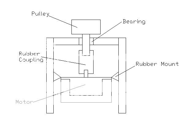
…The one attribute of the iron powder I don’t want to give up is the magnetic shielding. I will make a small iron filled enclosure for the motor. This will be suspended by soft mounts, and the motor shaft “soft” coupled to the pulley shaft.
After watching the rock solid speed stability of my AC supply/motor combo, I am more convinced than ever that a synchronous motor is the way to go…if the noise level can be brought down to that of a small DC motor. I’m fairly confident (past failures preclude being “very confident”) that this mounting scheme will accomplish this…we’ll see.
Casey
When I first fired it up I had MORE vibration than when the motor was plugged into the wall...I was confused/depressed for a couple minutes until I realized that the lagged phase provided by the run cap was half the voltage of the primary phase (for a 90 deg. phase shift, the caps reactance has to equal the load reactance, thus a 50% voltage drop). Once I lowered the lagged phase voltage, the vibration dropped to its previous level…unfortunately it wasn’t lower than its previous level.
I have lost count how many times I thought I had the motor vibration problem licked ( I would have to re-read the thread to see how many times I yelled “Eureka”). It seems I have been shuffling the vibrational energy around, as opposed to eliminating it. After thinking about it for a while, I have concluded that my iron filled enclosure isn’t the best route. First off, it isn’t working as well dampening the vibration as it was when first assembled. I believe the constant vibration of the motor has “packed” the iron powder so that it no longer moves around, dissipating the energy like it did when it was first filled. It’s essentially a solid block now. Second, by increasing the effective mass of the motor, I have lowered the resonance of the mounts I have come up with below that of the motor vibration. As I understand it, the noise to be isolated needs to be below the resonance of the suspension (opposite of what I have now), otherwise it passes through. And finally, I found that the vibration is directly related to belt tension due to the side thrust on the motor bearing. Before I had my strobe, I thought this was a simple matter of not running the belt so tight. I would play around with the tension until I found the spot the seemed tight enough, but had the lowest vibration. Well, the strobe has shown that it only “seemed” tight enough…if its loose enough to minimize vibration, the belt slips slightly, lowering the speed.
This is what I plan to try next…
…The one attribute of the iron powder I don’t want to give up is the magnetic shielding. I will make a small iron filled enclosure for the motor. This will be suspended by soft mounts, and the motor shaft “soft” coupled to the pulley shaft.
After watching the rock solid speed stability of my AC supply/motor combo, I am more convinced than ever that a synchronous motor is the way to go…if the noise level can be brought down to that of a small DC motor. I’m fairly confident (past failures preclude being “very confident”) that this mounting scheme will accomplish this…we’ll see.
Casey
Hi Nordic,
Yep..the point of the dual plinth was to accomplish this in a more compact space. The main problem I have is the more I isolate the vibration from the bottom plinth, the more energy there is to excite the mylar belt. Since I decouple the vibration from the base, it leaves all the energy to be transfered to the belt, and since my belt is a piece of tight mylar..BZZRRZZRRZZRR. Kind of like the comb/tissue paper kazoo I made in the 3rd grade. My hope is with the knew mounting scheme, the motor can vibrate to its hearts content, but be unable to transfer the noise to either the mount or the belt...time will tell.
Casey
Ever considered an offboard motor... I think some of the pictures I posted before included some nice example... the only contact the have with the platter is through the silkstring itself....
Yep..the point of the dual plinth was to accomplish this in a more compact space. The main problem I have is the more I isolate the vibration from the bottom plinth, the more energy there is to excite the mylar belt. Since I decouple the vibration from the base, it leaves all the energy to be transfered to the belt, and since my belt is a piece of tight mylar..BZZRRZZRRZZRR. Kind of like the comb/tissue paper kazoo I made in the 3rd grade. My hope is with the knew mounting scheme, the motor can vibrate to its hearts content, but be unable to transfer the noise to either the mount or the belt...time will tell.
Casey
I would ike to congratualte you on taking on such a difficult project. From the photographs of the milling work, it looks like you have a highly sophisticated talent with tools. I on the other hand can barely handle drilling a hole perpendicular to a surface. Show us the results of the finished product
Hello Hector,
Thank you for the kind words
I will indeed show the finished product..when I have a finished product I honestly believed I would be listening to my albums long ago, but with the unforseen problems, and the growing list of "features", it has taken considerably longer than anticipated. On the up side, I have learned a lot, and I should have a table I can be proud of.
Casey
Thank you for the kind words
I will indeed show the finished product..when I have a finished product
I honestly believed I would be listening to my albums long ago, but with the unforseen problems, and the growing list of "features", it has taken considerably longer than anticipated. On the up side, I have learned a lot, and I should have a table I can be proud of.Casey
What a piece of work
I have just finished reading this thread, what an inspiring piece of work.
I am just getting into turntable DIY myself with the re-boxing of an old Thorens TT and finding that enough of a job. This weekend I shall attack it with renewed vigour knowing what a trivial job it really is.
Can't wait for the pictures of the finished job.
R.
- Status
- This old topic is closed. If you want to reopen this topic, contact a moderator using the "Report Post" button.
- Home
- Source & Line
- Analogue Source
- Corian Turntable Fun