Absolutely incredible work. how many man hours so far? have you calculated (i bet you have)
I am a bit upset about the lack of titanium though")
its not as hard to work as they would like you to think especially if you machined drill stock!
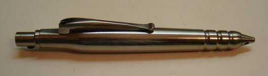
I made this fatty pen from ti.
I am a bit upset about the lack of titanium though
its not as hard to work as they would like you to think especially if you machined drill stock!
I made this fatty pen from ti.
Attachments
Hello neutron7
That's kind of you to say, thank you.
This project has clocked a few, I couldn't tell you how many exactly, hundreds for sure. I always want things done faster than they end up being..keeping a tab of how long this or that takes would take the fun out of it for me.
As am I. I keep asking the stocking clerk at Home Depot to start carrying it. No luck yet.
Very "Buck Rogers" . It looks like something out of early sci-fi. Nice work.
-Casey
Absolutely incredible work.
That's kind of you to say, thank you.
how many man hours so far? have you calculated (i bet you have)
This project has clocked a few, I couldn't tell you how many exactly, hundreds for sure. I always want things done faster than they end up being..keeping a tab of how long this or that takes would take the fun out of it for me.
I am a bit upset about the lack of titanium though
As am I. I keep asking the stocking clerk at Home Depot to start carrying it. No luck yet
.I made this fatty pen from ti.
Very "Buck Rogers" . It looks like something out of early sci-fi. Nice work.
-Casey
I’m starting to grow weary of chasing motor problems..
Over the holiday, between last minute shopping and family dinners, I stole some time to finish up my motor…or so I thought. While fitting the wiring, I ran it to test out the connections, and HEARD FARGING NOISE!! I traced it to the spindle transmitting bushing scrub. At first I thought I managed to get a piece of crud in my spindle bushing, but it didn’t take long to figure out my “academic” motor noise was anything but. It had increased exponentially. I broke the motor assembly down to investigate, and the first thing I found was the spring coupler had managed to compress itself about an 1/8” up the motor shaft. I loosened the set screw and let it relax back down the motor shaft, and re-secured it. It quieted up some, and became more intermittent in nature..coming and going. This time I removed the motor, and found that it had pushed out its assembly lube. On top of the bushing was a blob of grease, but not just any grease, sparkly grease, with little bronze filings, filings that used to be part of my motors bushing.
So I had 2 problems. First I got a dud of a motor. This thing made noise right out of the box, but I figured it needed to break in..not. The second problem was my spring coupler. Obviously it’s been doing a little dance to jack the collar up the shaft..that can’t be healthy for the motor. I attempted to save the motor by feeding it oil as it ran. I managed to quiet it up guite a bit, but it’s still noisy and needs to be replaced. Meanwhile, I will use it to drive the spindle while I true it up. To fix the coupler problem, I have come up with my fourth, and hopefully last design…
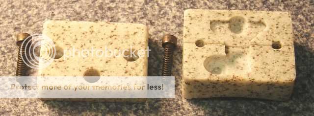
…I cut out three discs of Sorbothane with a punch, and glued them to the steel collars by first coating the disc stack with super glue, then JB Welding the super glue to the steel. It combines the best properties of the PVC and spring couplers.
On to the wiring…
It didn’t take long to go to plan “B”, and use a pigtail instead of winding the leads..not enough room. I decided that I needed a terminal block outside the motor housing, so I milled one out of Corion…
..and glued it to the housing by punching the housing, and roughing up the backside of the block to give the surfaces some “tooth”…

For the pigtail, I cut three conductors out of o floppy ribbon, and soldered and them to the leads and glued them down with super glue and RTV glue. I ran the wires through a hole in the housing/block, and stuffed a strip of Sorbothane above and below them in the hole…
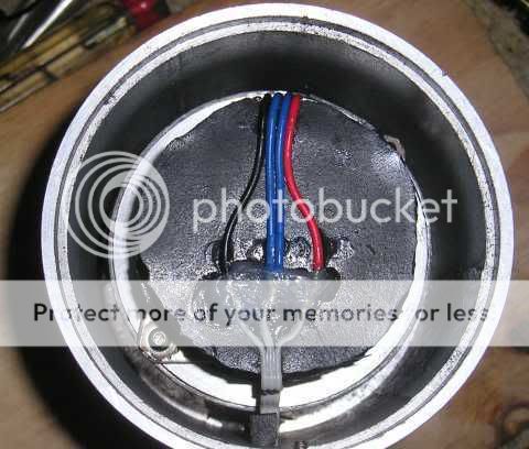
…I then wired in my power cord. It only needs to be 6”-8” long, so I took the advice I was given earlier and made my own. This is what it looks like before the cover goes on…

I milled the depth the of the cut-outs so that the cover would have .02” of crush to hold the wires in place with the cover on. Here it is with the finished termination…

Assembled with the new coupler, and the roached motor, it is still major quiet…you can only hear it if your ear is within an inch of the spindle. If I didn’t know that NO noise was possible, I could live with it…but I do, and I won’t. An order for a new motor will be placed. In the meantime, I am going forward
-Casey
Over the holiday, between last minute shopping and family dinners, I stole some time to finish up my motor…or so I thought. While fitting the wiring, I ran it to test out the connections, and HEARD FARGING NOISE!! I traced it to the spindle transmitting bushing scrub. At first I thought I managed to get a piece of crud in my spindle bushing, but it didn’t take long to figure out my “academic” motor noise was anything but. It had increased exponentially. I broke the motor assembly down to investigate, and the first thing I found was the spring coupler had managed to compress itself about an 1/8” up the motor shaft. I loosened the set screw and let it relax back down the motor shaft, and re-secured it. It quieted up some, and became more intermittent in nature..coming and going. This time I removed the motor, and found that it had pushed out its assembly lube. On top of the bushing was a blob of grease, but not just any grease, sparkly grease, with little bronze filings, filings that used to be part of my motors bushing.
So I had 2 problems. First I got a dud of a motor. This thing made noise right out of the box, but I figured it needed to break in..not. The second problem was my spring coupler. Obviously it’s been doing a little dance to jack the collar up the shaft..that can’t be healthy for the motor. I attempted to save the motor by feeding it oil as it ran. I managed to quiet it up guite a bit, but it’s still noisy and needs to be replaced. Meanwhile, I will use it to drive the spindle while I true it up. To fix the coupler problem, I have come up with my fourth, and hopefully last design…
…I cut out three discs of Sorbothane with a punch, and glued them to the steel collars by first coating the disc stack with super glue, then JB Welding the super glue to the steel. It combines the best properties of the PVC and spring couplers.
On to the wiring…
It didn’t take long to go to plan “B”, and use a pigtail instead of winding the leads..not enough room. I decided that I needed a terminal block outside the motor housing, so I milled one out of Corion…
..and glued it to the housing by punching the housing, and roughing up the backside of the block to give the surfaces some “tooth”…
For the pigtail, I cut three conductors out of o floppy ribbon, and soldered and them to the leads and glued them down with super glue and RTV glue. I ran the wires through a hole in the housing/block, and stuffed a strip of Sorbothane above and below them in the hole…
…I then wired in my power cord. It only needs to be 6”-8” long, so I took the advice I was given earlier and made my own. This is what it looks like before the cover goes on…
I milled the depth the of the cut-outs so that the cover would have .02” of crush to hold the wires in place with the cover on. Here it is with the finished termination…
Assembled with the new coupler, and the roached motor, it is still major quiet…you can only hear it if your ear is within an inch of the spindle. If I didn’t know that NO noise was possible, I could live with it…but I do, and I won’t. An order for a new motor will be placed. In the meantime, I am going forward
-Casey
I forgot to mention a few things in my last post.
In the spirit of firming up the motor's mount to minimize any future stress on it's (and more importantly, it's slated replacement), I removed the Sorbathane washers between it and the bottom ring. This was a "why not?" move to begin with, and not part of the original plan..it hasn't seemed to make a difference.
Also, I have discovered that the stethoscope is a useful tool, but not the last word. The noise I hear by placing my ear very near the spindle is not detectable with it. Pressing a screwdriver handle firmly on the ear and placing the shaft on the surface I can hear it..barely. I can hear the slightest hint of motor noise this way as well. This actually a relief in a way. Absolutes in mechanics, as in electronics, never happens in the real world, and I was starting to think I was nuts This noise isn't being transmitted to the plinth however using the same procedure. I think this may be similiar to listening through a wall with a glass, that is, I think I'm hearing the airbourne noise from the motor. Originally, I had planned to line the housing with Sorbothane for just this reason, but, after my earlier experience decided it wasn't needed. I also turned the top down to inlay a piece on it. I will now add the Sorbothane to see if it makes a difference..more out of curiosity than anything else.
Currently, even with the defective motor, it is quiet enough by any "normal" standard..nothing (that I can detect) is being transferred to the plinth it sits on. I just wan't to see how far it can be taken..I know, I'm being obsessive
-Casey
In the spirit of firming up the motor's mount to minimize any future stress on it's (and more importantly, it's slated replacement), I removed the Sorbathane washers between it and the bottom ring. This was a "why not?" move to begin with, and not part of the original plan..it hasn't seemed to make a difference.
Also, I have discovered that the stethoscope is a useful tool, but not the last word. The noise I hear by placing my ear very near the spindle is not detectable with it. Pressing a screwdriver handle firmly on the ear and placing the shaft on the surface I can hear it..barely. I can hear the slightest hint of motor noise this way as well. This actually a relief in a way. Absolutes in mechanics, as in electronics, never happens in the real world, and I was starting to think I was nuts
This noise isn't being transmitted to the plinth however using the same procedure. I think this may be similiar to listening through a wall with a glass, that is, I think I'm hearing the airbourne noise from the motor. Originally, I had planned to line the housing with Sorbothane for just this reason, but, after my earlier experience decided it wasn't needed. I also turned the top down to inlay a piece on it. I will now add the Sorbothane to see if it makes a difference..more out of curiosity than anything else.Currently, even with the defective motor, it is quiet enough by any "normal" standard..nothing (that I can detect) is being transferred to the plinth it sits on. I just wan't to see how far it can be taken..I know, I'm being obsessive
-Casey
valveitude said:
Also, I have discovered that the stethoscope is a useful tool, but not the last word. The noise I hear by placing my ear very near the spindle is not detectable with it. Pressing a screwdriver handle firmly on the ear and placing the shaft on the surface I can hear it..barely. I can hear the slightest hint of motor noise this way as well. This actually a relief in a way. Absolutes in mechanics, as in electronics, never happens in the real world, and I was starting to think I was nuts
Currently, even with the defective motor, it is quiet enough by any "normal" standard..nothing (that I can detect) is being transferred to the plinth it sits on. I just wan't to see how far it can be taken..I know, I'm being obsessive
-Casey
That's why I listen to the only thing that really matters - the noise being transmitted through the stylus. This assumes, of course, that noises not transmitted throught the stylus are not audible directly. If you want to increase the sensitivity and get a quantitative measurement, you could hook up the output of your rig to a O-scope. But, I'd guess that a computer sound card with software to display the output would be more than adequate.
Sheldon
That's why I listen to the only thing that really matters - the noise being transmitted through the stylus.
Well, if I had a stylus..or a cart..or a arm set up on the table, this would be the method of choice
In their absence, I am using what I have. That and experience with relative noise levels. The Idea is, if I can get the noise below the threshold of hearing mechanically on the bottom plinth, by the time whats left makes it through the lead shot pods to the top plinth, and then through the Corion/lead platter, it will be so weak as to be irrelevant...we'll see.
Once the table is basically complete, it will be moved out of the grimey metal shop into the electronic shop for testing/tweeking
-Casey
valveitude said:The Idea is, if I can get the noise below the threshold of hearing mechanically on the bottom plinth, by the time whats left makes it through the lead shot pods to the top plinth, and then through the Corion/lead platter, it will be so weak as to be irrelevant...we'll see.
-Casey
Your methods will work, I have no doubt of that. No noise, means no noise to transmit to the stylus. Testing with a stylus allows you to ignore noises that don't make it to that point. You don't even need a real arm. A cheap stylus taped to a stick would serve the purpose.
Sheldon
A cheap stylus taped to a stick would serve the purpose.
Your correct of course. I have a long weekend coming up, and I may just cludge something together. I think I still have a cart rattling in a drawer somewhere. I dont have a functioning phono pre either, but I do have a bag-o-opamps I could scab a phonoclone together with..hmm. An Lm386 driving some headphones added to it would make a dandy battery powered test set.
I'll inventory my parts, and see if I got all I need.
-Casey
A quick pricing FYI...
I originally purchased my Hurst AB3005-001 motor directly from Hurst's website, and after S&H, it came to within pennies of $80...ouch. For my replacement, it was suggested I try Grainger's site, they list it at $40.15 +S&H. Knowing that there is a Grainger affiliate in the town I work in, I gave them a call, and was quoted $28.91..delivered to there counter!!! It will be here tomorrow.
It doesn't always pay to do buisness online.
-Casey
Hi Casey
Sounds like you are having a fun Christmas - I havent been able to get within 3 yards of any of my projects. Too many kids, grandkids and such Lots of listening, tho...
With all of the effort you are putting into this zero-noise table, I think you ought to do some really accurate noise measurements. When the drive and platter are functional, email me and I will mail you my Wow & Flutter Meter and test recording. When you are done measuring your certain-to-be-silent table , you can send it back. It is a really accurate meter made in the late 80s and is nearly unused.
All you will need to do is jury-rig an arm and cartridge and feed the output into the meter and it will tell you exactly what the active vibrations are. The frequency and period of the measurements will tell you which parts (main bearing, motor, etc.)are generating noise. Since there will be none, may be a waste of postage
Happy New Year!!!!
Jess
Sounds like you are having a fun Christmas - I havent been able to get within 3 yards of any of my projects. Too many kids, grandkids and such
Lots of listening, tho...With all of the effort you are putting into this zero-noise table, I think you ought to do some really accurate noise measurements. When the drive and platter are functional, email me and I will mail you my Wow & Flutter Meter and test recording. When you are done measuring your certain-to-be-silent table
, you can send it back. It is a really accurate meter made in the late 80s and is nearly unused.All you will need to do is jury-rig an arm and cartridge and feed the output into the meter and it will tell you exactly what the active vibrations are. The frequency and period of the measurements will tell you which parts (main bearing, motor, etc.)are generating noise. Since there will be none, may be a waste of postage
Happy New Year!!!!
Jess
Hey Jess,
On the TT front, I was..right up to the point I discovered my over priced Hurst motor took a dump. The family/friends aspect of the holiday was great all the way through.

That is an incredibly generous offer Jess and I will take you up on it. No telling when I'll be ready for it though, I would be hesitant to track your test record unless I had a reasonably accurate arm set up..the records for these setups are harder to replace than the equipment.
Out of curiousity, whats the make/model? I may have used one in a previous life.
-Casey
Sounds like you are having a fun Christmas
On the TT front, I was..right up to the point I discovered my over priced Hurst motor took a dump. The family/friends aspect of the holiday was great all the way through.
When the drive and platter are functional, email me and I will mail you my Wow & Flutter Meter and test recording. When you are done measuring your certain-to-be-silent table , you can send it back. It is a really accurate meter made in the late 80s and is nearly unused.
That is an incredibly generous offer Jess and I will take you up on it. No telling when I'll be ready for it though, I would be hesitant to track your test record unless I had a reasonably accurate arm set up..the records for these setups are harder to replace than the equipment.
Out of curiousity, whats the make/model? I may have used one in a previous life.
-Casey
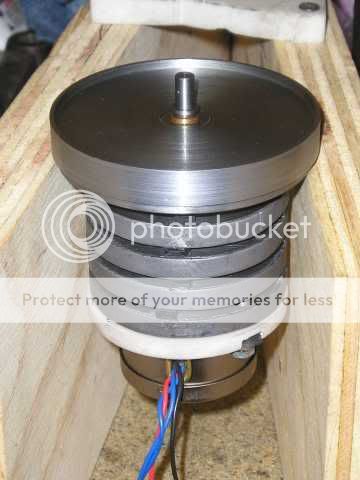
I picked up my new motor Friday on the way home from work. After letting it run for an hour or so to make sure all was well, I mounted it on my noise trap. You can imagine the thrill I experienced when I plugged it in and heard bushing scrub!! Clearly I had another problem. Gently pushing the motor around on its mount, I found I could vary the noise quite a bit. Tearing it down to investigate I found my problem. When I had shimmed the ring assembly square with the top plate, I had it upside down. The weight of the rings/motor was compressing the rubber, I had assumed the rubber would expand when hung at the same rate…oopsies. Due to the inconsistencies of the glue contact points (how far up the sides of the rubber blocks the glue migrated), it was off quite a bit from square when hanging (around .05”). I actually felt good about this..I had found the mode of failure for the first motor. By having the motor shaft running with a angular force applied, it cocked the shaft over so that the only contact points on the bushing was on one edge at the top, and the opposite edge on the bottom..metal to metal. The compliance of the spring coupler did a nice job of concealing the problem, but the new rubber coupler is less tolerant of sloppy work. Now that I know what happened, it was time to figure out how to keep it from happening again. I figured I had 2 options, A) I could spend an eternity chasing the problem with more shims, or B) I could fabricate an adjustable motor mount..I chose “B”…

..I cut out a circle of ¼” Corion, and routed out a cutout with my new rotary tool I found under the Christmas tree (thanks family ) to inlay a piece of Sorbothane for the motor to rest against. In addition to the two nuts that hold the disc/motor to the assembly, I drilled/tapped two holes 90 deg. from the fasteners to accommodate 6-32 set screws. The nuts pull the motor towards from the mount, and the set screws push away. In this way, I can fine tune the pre-load , and angle of the motor shaft. Once the motor was mounted back on, I cobbled together a test set up from a couple of wood blocks set up as a kinda-horn to amplify any noise…
…It worked surprisingly well. At one point I heard a “loud” noise with my ear next to the running motor that turned out to be my shirt collar brushing up against the wood. With the motor running, I adjusted the mount as best I could for minimum noise. I then averaged the distances of the four contact points from the top plate while hanging, and adjusted them to within aprox. .005” from each other. Setting it back down on the jig, it was quieter than it ever was before outside of the housing. The Sorbothane gasket pressed up to the motor really cut down the noise at the source, making the rest of the assembly all the more efficient.
Having successfully addressed the bushing problem, and making an improvement with the noise level in the proccess, I turned my attention back to the housing…

…I decided that if I didn’t line the inside of the housing with Sorbothane, I would always wonder if it would have made a difference or not. To save myself from the future angst, I went ahead and did it. I had to cut four slots to allow a screwdriver to reach the top from the bottom for disassembly, and I had to skin a little off the surface for clearance of the motor. I then remounted the assembly in the housing, and rewired it..

…Its tight, but the rings/motor have the room they need to vibrate freely.
I now moved on to where I was before the alignment problem reared its head..finishing the housing. I spent a lot of time this past weekend making little parts out of big pieces, or big ones out of lots of small pieces glued together. First up, the .3” thick bottom plate out of the same 5/8” plate I made the top one out of…

…The threaded hole in the middle is so that I can “lock” the suspension with a 3/8” bolt for moving/shipping, I reasoned the suspension couldn’t handle the bouncing around during a future move. The two threaded holes on the edge are to jack the plate back off for disassembly. The alignment plate wasn’t accounted for in the original plan, so I had to cut a recess to clear the motor. The fit was a little looser than planned, so I sealed it with nail polish. It worked out fine…

Now that the motor is finally together, I focused on truing up the pulley spindle. The first thing I had to address was protecting my exposed pulley bushing from the metal filings the grinding would generate. After thinking about it for a bit, I came up with a temporary seal made of leather in a Corion disc I taped with aluminum tape over the pulley shaft…

I then went to work making an adapter to mount my rotary tool to the quill of my drill/mill setup. This is where the making the big pieces out of small pieces came into play. I spent a solid 8 hour day gluing and dimensioning the stock needed to fabricate my new tool..time well spent I might add. I can see myself using this new addition to my shop a lot in the future. Here is the setup I used to true up the shaft…

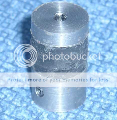
Since I needed to match the shaft to the pulley (opposite of how it’s normally done), I needed to make the pulley first. This was the biggest exercise of whittling a toothpick out of log I had ever done. Years ago, I bought some pieces of aluminum scrap ends from an aerospace machine shop. Among the pieces, there was this 3” square piece that was an incredible alloy. There wasn’t any markings on it so I can’t identify it, but it took over on hour to cut off an end with a hacksaw..this stuff is tough. I’ve been holding on to it ever since. I decided that the wear characteristics would be perfect for my pulley, even though it would be a shame to waste so much material for such a small piece. You gotta do what you gotta do. To illustrate how incredibly tough this stuff is I took a picture of the scarf left by the turning…

…If you’ve ever worked a lathe you would recognize what I’m talking about, if not, metal breaks off into little pieces as it peels off the stock..especially metals like aluminum. This stuff comes off as one continuous, long piece.
After fabbing the pulley, I had a hole to match the shaft to. I decided on a letter “A” bit for the bore, giving me a hole .235” in diameter. I skinned off a couple a tenths at a time until I had a perfect fit. It slips on easily, but has such a close fit that it creates a vacuum when you pull it off. Having tired of scaring up the shaft with the set screw, I used my new tool to grind in a flat…

…This also illustrated how important the seal was. If any one of the thousands of metal filings sitting on the top of the motor were to make its way into the bushing, it would have toasted it. Here is the freshly ground shaft after clean up, and removing the seal…

Here is a close-up of the pulley mounted…

…If you look closely, you can see the profile has a curve on the ends. My original pulley cut for the 300 rpm motor, had a more aggressive curve that covered the whole face. I found two problems with that. One, since Mylar doesn’t stretch easily, the contact area was only in the middle of the belt, and two, when Mylar does stretch, it stays stretched. This caused the belt to ripple on the edges after a short time. This time, I left the middle .4” flat, and filed in a progressive curve .1” in from either side. The first .05” from the center flat is curved very slightly, and gets progressive quickly after that.
Finally, other than the top inlay, a completed turntable motor…

(((continued on the next post..I exceeded the post limit)))
..I cut out a circle of ¼” Corion, and routed out a cutout with my new rotary tool I found under the Christmas tree (thanks family
) to inlay a piece of Sorbothane for the motor to rest against. In addition to the two nuts that hold the disc/motor to the assembly, I drilled/tapped two holes 90 deg. from the fasteners to accommodate 6-32 set screws. The nuts pull the motor towards from the mount, and the set screws push away. In this way, I can fine tune the pre-load , and angle of the motor shaft. Once the motor was mounted back on, I cobbled together a test set up from a couple of wood blocks set up as a kinda-horn to amplify any noise…
…It worked surprisingly well. At one point I heard a “loud” noise with my ear next to the running motor that turned out to be my shirt collar brushing up against the wood. With the motor running, I adjusted the mount as best I could for minimum noise. I then averaged the distances of the four contact points from the top plate while hanging, and adjusted them to within aprox. .005” from each other. Setting it back down on the jig, it was quieter than it ever was before outside of the housing. The Sorbothane gasket pressed up to the motor really cut down the noise at the source, making the rest of the assembly all the more efficient.
Having successfully addressed the bushing problem, and making an improvement with the noise level in the proccess, I turned my attention back to the housing…
…I decided that if I didn’t line the inside of the housing with Sorbothane, I would always wonder if it would have made a difference or not. To save myself from the future angst, I went ahead and did it. I had to cut four slots to allow a screwdriver to reach the top from the bottom for disassembly, and I had to skin a little off the surface for clearance of the motor. I then remounted the assembly in the housing, and rewired it..
…Its tight, but the rings/motor have the room they need to vibrate freely.
I now moved on to where I was before the alignment problem reared its head..finishing the housing. I spent a lot of time this past weekend making little parts out of big pieces, or big ones out of lots of small pieces glued together. First up, the .3” thick bottom plate out of the same 5/8” plate I made the top one out of…
…The threaded hole in the middle is so that I can “lock” the suspension with a 3/8” bolt for moving/shipping, I reasoned the suspension couldn’t handle the bouncing around during a future move. The two threaded holes on the edge are to jack the plate back off for disassembly. The alignment plate wasn’t accounted for in the original plan, so I had to cut a recess to clear the motor. The fit was a little looser than planned, so I sealed it with nail polish. It worked out fine…
Now that the motor is finally together, I focused on truing up the pulley spindle. The first thing I had to address was protecting my exposed pulley bushing from the metal filings the grinding would generate. After thinking about it for a bit, I came up with a temporary seal made of leather in a Corion disc I taped with aluminum tape over the pulley shaft…
I then went to work making an adapter to mount my rotary tool to the quill of my drill/mill setup. This is where the making the big pieces out of small pieces came into play. I spent a solid 8 hour day gluing and dimensioning the stock needed to fabricate my new tool..time well spent I might add. I can see myself using this new addition to my shop a lot in the future. Here is the setup I used to true up the shaft…
Since I needed to match the shaft to the pulley (opposite of how it’s normally done), I needed to make the pulley first. This was the biggest exercise of whittling a toothpick out of log I had ever done. Years ago, I bought some pieces of aluminum scrap ends from an aerospace machine shop. Among the pieces, there was this 3” square piece that was an incredible alloy. There wasn’t any markings on it so I can’t identify it, but it took over on hour to cut off an end with a hacksaw..this stuff is tough. I’ve been holding on to it ever since. I decided that the wear characteristics would be perfect for my pulley, even though it would be a shame to waste so much material for such a small piece. You gotta do what you gotta do. To illustrate how incredibly tough this stuff is I took a picture of the scarf left by the turning…
…If you’ve ever worked a lathe you would recognize what I’m talking about, if not, metal breaks off into little pieces as it peels off the stock..especially metals like aluminum. This stuff comes off as one continuous, long piece.
After fabbing the pulley, I had a hole to match the shaft to. I decided on a letter “A” bit for the bore, giving me a hole .235” in diameter. I skinned off a couple a tenths at a time until I had a perfect fit. It slips on easily, but has such a close fit that it creates a vacuum when you pull it off. Having tired of scaring up the shaft with the set screw, I used my new tool to grind in a flat…
…This also illustrated how important the seal was. If any one of the thousands of metal filings sitting on the top of the motor were to make its way into the bushing, it would have toasted it. Here is the freshly ground shaft after clean up, and removing the seal…
Here is a close-up of the pulley mounted…
…If you look closely, you can see the profile has a curve on the ends. My original pulley cut for the 300 rpm motor, had a more aggressive curve that covered the whole face. I found two problems with that. One, since Mylar doesn’t stretch easily, the contact area was only in the middle of the belt, and two, when Mylar does stretch, it stays stretched. This caused the belt to ripple on the edges after a short time. This time, I left the middle .4” flat, and filed in a progressive curve .1” in from either side. The first .05” from the center flat is curved very slightly, and gets progressive quickly after that.
Finally, other than the top inlay, a completed turntable motor…
(((continued on the next post..I exceeded the post limit)))
So how does it perform after the repairs/refinements? The only noise of any kind, that can be detected by any means at my disposal, is if I touch the spinning pulley shaft on the cartilage off my outer ear, I can barely make out some hum buried below the noise of the shaft rubbing the skin. I hadn’t planned this technique, I discovered it as I inched my ear ever closer to the spinning shaft. I have some very serious doubts that this can excite 20+ Lbs. of platter through the six inches or so of Mylar belt it would have to travel. I can no longer hear anything holding the housing to your ear, thanks to the Sorbothane lining the housing, and dampening the motor on it’s new mount. It isn’t running the table for the final exam until I modify the plinth for the added height of the new motor.
I realize I have been on the lunatic fringe combating noise here, but consider this. We spend countless hours minimizing power supply ripple in our phono preamps to levels considered insane in the past. Not because we hear it directly (unless there is a real problem), but because every time the noise level drops on the supply, we hear an improvement in overall clarity. My first foray into mechanical noise reduction was on a Dynaco ST-70 many years ago. The power transformer hum could be felt throughout the chassis. Knowing that tubes are microphonic, I reasoned that this couldn’t be good even if I couldn’t hear it. I remounted the tranny with rubber grommets between it and the chassis, and the results were very impressive. My roommates agreed that this simple mod resulted in the biggest improvement we had made to the amp... everything was better.
I believe the same principle applies here.
-Casey
Hey Casey
I have both referred to, and praised, this thread previously, but I thought I might just say here why I value it highly - it is for the same reason (for you boat people) why I value Philip Bolger: because he (and Casey) report all of their results fully and honestly.
This serves two functions: (1) it gives those of us who haven't gone through the experience the opportunity to understand the complexity of such "simple" acts as creating a motor mount; and (2), it demonstrates the difference between "hypothesis-result" and real-world messiness - e.g., first I heard the noise, then didn't - what's going on here?
I value both of these things, and to find them together is extremely rare. So Casey, thank you for both your honesty and your attention to detail - I'll continue to follow this thread until, as I'm sure you will, you get the results you are aiming for.
Regards.
Aengus.
Hey Aengus,
Thank you for your kind words of encouragement. It is not an easy thing to display ones errors/failures to the world, but in them lies the potential for real learning. When an idea comes together without a hitch, I smile smugly at my accomplishment, and move on learning nothing new. It’s when it goes to hell, and I endeavor to figure out why, that’s when the education begins. In the relatively short time I have been a member in these forums I have learned a great deal from the other members here..both from the success stories, and more importantly, from the designs that should have worked but didn’t. The long back and forth discussions that grow out of the unexpected results is where the true potential for knowledge resides. It has been my hope that I could give back to this community in some small way, your words have made it clear to me that I have, if in no other way, to show that theory and reality don’t always agree. As my Dad is found of saying “An architect can draw a house, but, it takes a carpenter to build one.”
On the topic of displaying my boo-boo’s, I forgot to mention a small problem that has come to light with my pulley shaft bushing design. Oh, it works fantastic..as long as you don’t blow the motor off with compressed air. I discovered just how susceptible it is to getting garbage in it. After blowing some shop crud off, I noticed a small noise coming from it. I had managed to blow enough oil out of it, that it lost it’s hydrostatic oil film. I put a couple of drops of oil around it to work in, and after a minute or so, the low level scrub was replaced by an unnerving "tinking" sound. It seems the new oil had carried a bit of dust in with it, carving a new, unintended micro-groove in the bushing. It worked itself out, and all is silent again, but it illustrates how exposed it is to the environment. In the future, I will take better care to ensure my bushings are better protected.
-Casey
Casey -
The 'Oracle Delphi' turntable is a fairly well-regarded turntable of some years now, yea ? Well, some will know of this fact, as I do (I own a Delphi MkIII) - The 3-phase (...yes, that's right, 3 ac phases driven ) motor is held in a chamber lined with guess what ?? Bingo !! ---> ***Sorbothane*** just as you've proven !
Also, just in case anyone out there wants to investigate it...I have kept (for a good few years now) a couple of VCR helical scanning head motors. How many phases are we talking about here? Nothing less than Four phases !
I wondered all those years ago whether these could be used in the good cause of TT drive.
Keep up the good work !
-Andy-
I'm afraid VCR drum motors are stepper motors rather than synchronous so their rotation isn't as smooth.
That's confusing. I thought stepper motors were synchronous. They don't slip relative to the drive frequency.
For some time I couldn't find any difference between a synchronous motor and a stepper motor, but there is one, and it's down to the shape of the stator pole pieces. A stepper motor has rectangular pole pieces so as to sharply define the magnetic flux and force the rotor to snap to a very precise position. Conversely, a synchronous motor has triangular pole pieces to blur the magnetic flux and move the rotor smoothly. Thus, although a stepper motor can be used as a synchronous motor (and they certainly don't slip), the rotation won't be as smooth.
NjoyTHEMUSIC-
Well..yea. And it’s purdy enough to qualify as “Audio Porn”…

So whadaya know..seems my quest/methods for a stable quiet drive hasn’t been so “looney-tunes” after all. I’m sure Oracle didn’t have to go to the extremes I did though, 3-phase motors are inherently much smoother than the 2-phase variety.
EC8010-
Is this true for all video drum motors ? Having replaced/aligned several consumer, as well as commercial VTR heads, I always thought they ran very smooth..never measured anything though, just my impression.
My own attempt at running a stepper as a synchronous, ala “Altmann”, seems to bare this out…very noisy.
-Casey
The 'Oracle Delphi' turntable is a fairly well-regarded turntable of some years now, yea ?
Well..yea. And it’s purdy enough to qualify as “Audio Porn”…
The 3-phase (...yes, that's right, 3 ac phases driven ) motor is held in a chamber lined with guess what ?? Bingo !! ---> ***Sorbothane*** just as you've proven !
So whadaya know..seems my quest/methods for a stable quiet drive hasn’t been so “looney-tunes” after all
. I’m sure Oracle didn’t have to go to the extremes I did though, 3-phase motors are inherently much smoother than the 2-phase variety.I have kept (for a good few years now) a couple of VCR helical scanning head motors...I wondered all those years ago whether these could be used in the good cause of TT drive.
EC8010-
I'm afraid VCR drum motors are stepper motors rather than synchronous so their rotation isn't as smooth.
Is this true for all video drum motors ? Having replaced/aligned several consumer, as well as commercial VTR heads, I always thought they ran very smooth..never measured anything though, just my impression.
For some time I couldn't find any difference between a synchronous motor and a stepper motor, but there is one, and it's down to the shape of the stator pole pieces... a stepper motor can be used as a synchronous motor (and they certainly don't slip), the rotation won't be as smooth.
My own attempt at running a stepper as a synchronous, ala “Altmann”, seems to bare this out…very noisy.
-Casey
- Status
- This old topic is closed. If you want to reopen this topic, contact a moderator using the "Report Post" button.
- Home
- Source & Line
- Analogue Source
- Corian Turntable Fun