Bernhard,
As I am eagerly awaiting the Maxon motors I built a kind of cart to put it in. To finish it I need to know:
1. I understand the diameter is 28mm but what is its height?
2. You wrote somewhere that you have to be careful how much sideload the motor gets. Can you tell me what the maximum safe force might be?
thank you
Attachments
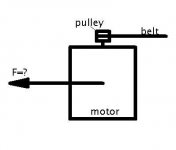
SIDELOAD
Hi Peterr,
2.In this respect i have to remind all of you intending to use a maxon that maxon specifies a maximum radial static load
of 5.5 Newton (at lever arm length 5mm, measured from the flange). Therefore i do not recommend belts with 1/2" / 12.7mm width.
Copyricht ice45.
I think this is what you're referring to.
Happy building,
Hi Peterr,
2.In this respect i have to remind all of you intending to use a maxon that maxon specifies a maximum radial static load
of 5.5 Newton (at lever arm length 5mm, measured from the flange). Therefore i do not recommend belts with 1/2" / 12.7mm width.
Copyricht
ice45.I think this is what you're referring to.
Happy building,
First: Hello everybody! Long time no see.
Second: line frequency variations. I have been building Nixie clocks - one of the thngs that has kept me from "hanging out" online - and these will show very directly the variance in line frequency. It seemed to me that the frequency here in Brooklyn, NY was very stable until recently (I have one such clock I have been using for two years.)
Lately it varies more widely than I was expecting - my clocks are sometimes off by five minutes in a day, and reversion to the mean does not seem to be happening either.
24 hours x 60 min = 1440
5/1440 = .00347 or 0.347%.
So on the order of half a percent at worst here from my recent experience. Probably audible to pitch sensitive folks.
If you use a strobe fired by the mains (many fewer parts - a neon bulb, a 100K resistor, and two clipleads!) all you are checking is that your turntable is tracking the mains frequency properly - I just did this with an AR XA I am refurbishing for a friend. In absolute measures, you are not learning anything, and if you are troubling yourself to use a DC motor, you deserve better - no reason to be dependent on the mains for your accuracy.
-j
STROBE
Hi,
Glad to see you back J.
For measurements I suppose you suggest a batttery powered strobelight?
In Europe mains frequency is very stable though from what I see
so far.
Ditto for the PS of the dc motor?
I heard some objections against the use of batteries for the motor unit,mostly along the lines that they don't last long and are a pain to keep charged correctly.
Any experienced good soul(s) around?
Ciao,
J Epstein said:Second: line frequency variations. I have been building Nixie clocks
Nixie tubes! This is cool. I have a small hang-up for these devices. They are so cute.
Hi,
P-A,you really deserved your enlightenment with me now!
For those unfamiliar with these:
They were widely used in balances to display the weight and such.
Inside the tubes (usually subminiature standard) you had heaterlike digits from 0-9.
They had this lovely orange glow when lit.
Although I have seen a clock that used these I never saw it working since someone had spilled coffee over it.
That thingie was really cool since all the tubes were molten into a translucent acrylic block.
Really supertech!
Cheers,
P-A,you really deserved your enlightenment with me now!
Nixie tubes! This is cool. I have a small hang-up for these devices. They are so cute.
For those unfamiliar with these:
They were widely used in balances to display the weight and such.
Inside the tubes (usually subminiature standard) you had heaterlike digits from 0-9.
They had this lovely orange glow when lit.
Although I have seen a clock that used these I never saw it working since someone had spilled coffee over it.
That thingie was really cool since all the tubes were molten into a translucent acrylic block.
Really supertech!
Cheers,
Hi,
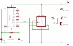
I am trying to make a strobe as per Bernhard's circuit, however I think perhaps it is not oscillating. The LED illuminates, but I see no 'freezing' on my strobe pattern (can see dimly under room light). I am using a 3.2768MHz crystal to get 100Hz output, and a HCF4060BE divider. As I do not have oscilloscope, is there any way I can tell if the 4060 is oscillating?.
I am trying to make a strobe as per Bernhard's circuit, however I think perhaps it is not oscillating. The LED illuminates, but I see no 'freezing' on my strobe pattern (can see dimly under room light). I am using a 3.2768MHz crystal to get 100Hz output, and a HCF4060BE divider. As I do not have oscilloscope, is there any way I can tell if the 4060 is oscillating?.
Some modifications and the circuit is now working fine. Final layout is as below. LED is a 3600mcd red, and gives a strong high contrast bar pattern with minimal fuzz. Circuit seems to work fine without using the second half of the flip-flop, so I'd be interested to hear any feedback on merits / demerits of this.
Attachments
- Status
- This old topic is closed. If you want to reopen this topic, contact a moderator using the "Report Post" button.
- Home
- Source & Line
- Analogue Source
- DIY TT: motor, motor PS, platter speed measurements