I'm getting somewhat frustrated with the single-stage SRPP RIAA amp. It has some sensitvity regarding the gain of the bottom fet in the SRPP.. It has too much infrasonic gain, and the distortion simulation at 10kHz sucks. Me thinks this approach may b trying to do too much with too little.
For the time being, I'm going to back off of this approach and use a design with two stages of RIAA gain for my studio preamp. The first stage is a tried-and-true cascoded common source amp, which with the 2SK117, has a simulated THD of 0.02%, overwhelmingly 2nd order - pretty good for such a simple circuit. The second stage is a resistively loaded SRPP -I'm using the trim pot as the SRPP load to save parts. The third stage is a lean, clean unity gain buffer stage that will drive a transformer to generate a balanced output to feed the studio A-D converter. The rest is a hot-shot shunt regulator that supplies +30V to the RIAA and line stages. I'll hack up the studio design I already have to breadboard this approach, and graft it in to one of my Technics 1200s loaded with an Ortofon GT cartridge in order to check out the sound.
For the time being, I'm going to back off of this approach and use a design with two stages of RIAA gain for my studio preamp. The first stage is a tried-and-true cascoded common source amp, which with the 2SK117, has a simulated THD of 0.02%, overwhelmingly 2nd order - pretty good for such a simple circuit. The second stage is a resistively loaded SRPP -I'm using the trim pot as the SRPP load to save parts. The third stage is a lean, clean unity gain buffer stage that will drive a transformer to generate a balanced output to feed the studio A-D converter. The rest is a hot-shot shunt regulator that supplies +30V to the RIAA and line stages. I'll hack up the studio design I already have to breadboard this approach, and graft it in to one of my Technics 1200s loaded with an Ortofon GT cartridge in order to check out the sound.
Attachments
Here is a Creek-style gain cell that doesn't try to eke all the gain for an RIAA preamp out of one stage. This particular example is adjusted for ~30X gain, good enough for the second half of a 2-stage passively equalized RIAA preamp. Appropriate input devices include the 2N5459, the PN4303, or the 2SK30A. A cascoded common source stage with a 2SK170 or 2SK117 might be as the front end gain cell. Simulation is OK as far as it goes, though the simulator chokes up using the time resolution I've been using for other circuits. I may have to measure this one real-world.
Attachments
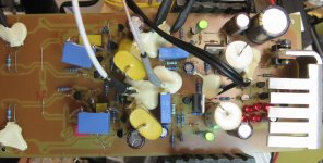
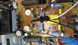
Attached is a picture of the hacked-up prototype board with circuit per the one in post #222. The puddles of hot melt are strain relief for leads going to input, level adjust, and output. I've had to do a little debugging to smoke out some wrong/bad connections (always a problem when you're hacking an existing PC board to accomodate a different circuit). With luck, I'll be running some response curves this afternoon. Once the board is working and characterized, I plan to hook it up to one of my Technics 1200s to optimize the cartridge termination R and C at the input.
Attachments
Last edited:
Just because all the lights are on, doesn't mean that everybody's home... I had a couple of FUs to fix to make this lash-up fully operational - one missing jumper and a reversed cable (if you ground the output of an amp stage, it stands to reason you won't get much output - duh....). At any rate, I'll be carting this thing back to work tomorrow to try and get some response curves. If those look ok, it's time for the Technics 1200.
Attached are the gain-phase curves for the circuit shown in post #222. Gain is a little high at ~40dB at 1kHz, but I can trim that some at a later date. Matching between channels is ~0.1dB, not bad for an open loop RIAA preamp. Next up will be cartridge tuning and listening tests.
Attachments
Yee-Haw - I just got the preamp pictured in post 222 hooked up to an aux input of my DJ mixer (Furman DJM-8, like a baby Rane), fed by one of my Technics 1200s with a newly installed Ortofon GT cartridge. The background is quiet enough so that I can hear the TT cogging on silent passages. Sound is crisp and engaging, even with my beat-up Sony headphones - if I hooked up my AKGs, I probably wouldn't be able to tear myself away. Next up is a little more precise alignment of the cartridge and some input capacitive trimming using the HiFi News test record. Right now, the input is terminated with just a 47k5 resistor and the capacitance from the TT leads and input fet. It's early days yet, but this circuit looks like a keeper.
Here's the latest version of the master studio preamp board. There will be 3 in a 1U chassis, as there are 3 turntables in the KFJC master studio. One boards check out ok, the other has a low channnel, which I think is traceable to the SRPP stage. Will fix that and proceed to stuff and test the 3rd board. The heat sink for the onboard regulator is a 75 cent pin-fin CPU heat sink that does a really nice job.
Attachments
The caps used are UCC KZE series, which is pretty low impedance (28 mohm/cap for the 330uF/50V). Smaller caps in parallel are lower impedance than one big one (21 mohm), with a higher frequency ESR zero. If I'm spreading out the cap loading of the shunt regulator between 4 caps, why not put each cap where it will do the most good? Surely you wouldn't lump all the decoupling for an opamp-based board in one place and not use individual decoupling for each package...
That's not what I am trying to say.
You have two channels .
Each has it's own decoupling.
But the two channels share the same power rail.
Why?
Would it be better to add a series resistor into each of the 2 power rails before the individual decoupling. This RC will help separate the two power rails and interaction between the two amplifiers.
I will be posting a separate thread on this, as the preamp no longer has any SRPP content whatsoever, but I've been working off and on on a new studio RIAA preamp for the radio station where I DJ (KFJC) using discrete jfets and mosfets. It Incorporates some of the things I've been messing with over the past (is it 5 or 6 years? is it more?), anyway, discrete stuff I've been messing with for a good long while.
Attached is a schematic that's likely to make it into the box soon. This is a complete module that combines an RIAA preamp and line driver (both channels) on one board with a common regulator that will run off a +40V raw supply (outside the box). There will be 3 of these modules in the case to handle the three TTs we have in our master studio. This will replace our current preamp that uses a hodgepodge of discretes and opamps, and is considerably more complicated under the hood. I'll probably recap that one, fix its issues, and keep it around as a backup (it was a learning experience).
I started out with a simple common source/SRPP combination that ran into bias centering issues (maybe related to shi**y fets). The second stage got replaced with an augmented feedback pair stage that's a lot more consistent, especially when I bother to stuff the right part values...
This project got sidelined for a while so I could work on stuff for Burning Amp, but now that that's over I can concentrate on it again - I'd like to have it working in the studio before Christmas (this Christmas, that is).
Attachments
Attached are the gain-phase plots I ran on one of the modules this afternoon. The matching is excellent. Next up is to run one of these into my DJ mixer for a while so I can listen to it working with the cartridge we plan to use to replace the Stantons currently in our studio, with the aim of tweaking in the cartridge loading values.
Attachments
I've lately been working on an RIAA preamp for MM duty using a simple cascoded common source amp at the input (using the 2SK117 for best noise vs. input capacitance), with an SRPP second stage for lower distortion than the standard "Pacific" style preamp that uses two common source stages.
I've been having trouble getting the SRPP stages to balance out at 1/2 VCC, and putting the blame on the fets. After some thought, I now realize that a jfet SRPP will be at best a touchy beast, as it's like trying to stack two pentodes - the more "pentodish" the device (as in acting like a true current source), the touchier it will be. I ended up balancing the stages with a minor amount of trim across the device source resistors as needed (not much - ~200 k across a 332 ohm source resistor was enough). Another way to promote centering might be to drop a largish resistor (start with 100k?) across each stage from the drain to the bottom of the source resistor. I'll try it when I have the time.
At any rate, this got me thinking. Folks building triode SRPP stages never seem to report difficulties with centering - what could be done with a more triode-like solid state device? SITs would be a natural candidate, but I don't have any, though there are some Russian small-signal devices available. Another expedient would be to fake a SIT using a mosfet and feedback. That's what I did.
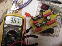
Attached is a picture of a breadboard of an SRPP inverting preamp using a couple of pairs of IRF610 fed back for that fine triodish "fake SIT" characteristic. I threw the little thing together in an afternoon from available parts, guessing roughly about needed component values based on simulations already done. I deliberately made no attempt to select the mosfets involved, but output centering and was still excellent. I'll post a schematic and test results as things develop. This project will probably get split off into a separate thread, as the circuits involved appear to be more suitable for line duty rather than for phono stages. The meter in the picture is reading the voltage across one of the source resistors (33.2 ohm) - the measured voltage points to a bias current of about 12 ma.
I've been having trouble getting the SRPP stages to balance out at 1/2 VCC, and putting the blame on the fets. After some thought, I now realize that a jfet SRPP will be at best a touchy beast, as it's like trying to stack two pentodes - the more "pentodish" the device (as in acting like a true current source), the touchier it will be. I ended up balancing the stages with a minor amount of trim across the device source resistors as needed (not much - ~200 k across a 332 ohm source resistor was enough). Another way to promote centering might be to drop a largish resistor (start with 100k?) across each stage from the drain to the bottom of the source resistor. I'll try it when I have the time.
At any rate, this got me thinking. Folks building triode SRPP stages never seem to report difficulties with centering - what could be done with a more triode-like solid state device? SITs would be a natural candidate, but I don't have any, though there are some Russian small-signal devices available. Another expedient would be to fake a SIT using a mosfet and feedback. That's what I did.
Attached is a picture of a breadboard of an SRPP inverting preamp using a couple of pairs of IRF610 fed back for that fine triodish "fake SIT" characteristic. I threw the little thing together in an afternoon from available parts, guessing roughly about needed component values based on simulations already done. I deliberately made no attempt to select the mosfets involved, but output centering and was still excellent. I'll post a schematic and test results as things develop. This project will probably get split off into a separate thread, as the circuits involved appear to be more suitable for line duty rather than for phono stages. The meter in the picture is reading the voltage across one of the source resistors (33.2 ohm) - the measured voltage points to a bias current of about 12 ma.
Attachments
Last edited:
For the last word on this "Schade SRPP" untill I move this discussion into a new thread, here's the square wave response of the breadboard pictured above (rising and falling edges). The top waveform is the response, and the bottom is the excitation. The little wretch is quite fast, but the overshoot will have to go. I have an idea of the compensation that might straighten things out, and will try it and report later.
Attachments
I've been having trouble getting the SRPP stages to balance out at 1/2 VCC, and putting the blame on the fets.
Perhaps, the most reliable means to address this problem is to apply fixed-biasing to the upper JFET, turning it in to a gyrator. You could create a bias reference voltage by dividing the supply in half with a string of two very high value resistors. Tap the midpoint of this string for biasing the upper JFET's gate. Then, A.C. couple the upper JFET gate to the bottom of it's source resistor, at the lower JFET's drain). You can use a small value capacitor because of the high impedance terms involved.
Also, I believe the output impedance of a JFET SRPP will be very high whether taken from the upper JFET's source terminal, or the lower JFET's drain terminal. Triode based SRPP circuits are different in this way because triodes exhibit an internal plate resistance (Rp).
Last edited:
- Home
- Source & Line
- Analogue Source
- JFET SRPP RIAA Preamp