Hi. I'm looking for the schematic or any technical information on the optionnal Michell HR supply for their DC motor turntable. it is supposed to be a great upgrade to the original small DC wall adapter. This HR supply is quite expensive. It contains what is called "Never-Connected" supply. After a search on the net I collected these informations:
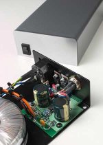
1-The HR supply uses "Active-Rectification" followed by a solid state regulator, possibly a standard LM317. It has a variable DC 9V output, so the DC motor speed can be adjusted. It has High current capacity, specs unknown, possibly higher than the standard wall adpater 9V dc supply. It is suing also a toroidal transformer. See image.
2-The HR supply image gives a few clues about is circuitry. We see rectication diode, possibly Hi-Speed recifiers, and possibly two low ESR caps. The "Active rectification" is probably use after the first diode rectification. It is using possibly the MAX797 IC's and a FET as active rectification part. The LM317 or LT variant (low drop-out) rectifier and the FET are probably mounted on the supply's back.
3-The "Never-Connected" principle is basicly a DC supply using "Active rectification". This principle well known for numerous years use active FET switch to rectify the AC voltage. The advantge are:
Linear (sinusoidal) current and voltage load
THDU, THDI small
Two way energy flow (source-load-source), energy recuperation
In case of active rectifier breakdown can the device operate normally as an uncontrolled rectifier
cosf regulation
Output voltage stabilization
It is probably a good start to use this desing:
-Toriodal transfo + high speed rectifiers + Panasonic FC low ESR caps, small MOV at the input of the transfo.
-MAX797 + FET active rectification, set at maybe 12V
-Final LT1085 low drop-out adjustable regulator, set at 9V +/-5% potentiometer adjustement (for speed fine tuning)
-Small FC cap at the ouptput with MKS Wima bypass cap (as the image is showing)
Any comments are welcome...
Attachments
what you suggested is certainly interesting. i'm not sure if i have the technical ability to provide inputs though...
the lm317t is used in this supply. you can see if clearly if you zoomed in the pdf of the hifi news march 2004 review. the to220 device beside the lm317t looks like an IRF transistor.
there's also another to220 device on the board. possibly an adjustable regulator capable of regulating from 24v to 5v.
some stuff abt the NC supply.
1. input voltage from 10vac for single rail, 9vac min.
2. has a full bridge rectifier.
3. a pot to make output variable to from below 5 volts to at least 24 volts.
4. 16v 4700uF x 2 caps in post rectifier section (diy NC boards have 16v 22000uF x 1 cap per rail)
the dc-dc buck circuit requires a choke. i don't see this on the NC images. maybe they are using a smd choke, not the regular ones.
i wonder what others have to say.
Algar_emi said:3-The "Never-Connected" principle is basicly a DC supply using "Active rectification". This principle well known for numerous years use active FET switch to rectify the AC voltage. The advantge are:
If by 'Active rectification' you are referring to what is also known as synchronous rectification then the NC principle might be a little more sophisticated than that. See J. Carr's post after this one:
http://www.diyaudio.com/forums/showthread.php?postid=151148#post151148
In low current, low voltage supplies like these synchronous rectification doesn't give enough advantage in terms of losses to be worthwhile. However a multiple cap, multiple switch topology should give noise improvements over standard linear supplies. I should mention that I haven't tried these circuits (or used NC stuff) but hope it might be of use.
James
Instead of persuing the never connected supply you may ponder classical rectification, followed with CLC filtering and then two tiers of regulation. First something like an LM317, then an opamp-based series regulator with armature current feedback and thus compensation for the motor coil resistance as sort of active speed control.
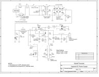
I was able to get some more info on the HR supply. Here a first draft of possibly how it is working. I don't pretend that is working but it is a start to discuss the principle.
From the article, it is mentionned that a comparator drive a capacitor charging FET according to some phase angle duration of the 60Hz AC voltage.
This schematic shows this principle.
Any comments on this circuit and or additons
Thanks....
From the article, it is mentionned that a comparator drive a capacitor charging FET according to some phase angle duration of the 60Hz AC voltage.
This schematic shows this principle.
Any comments on this circuit and or additons
Thanks....
Attachments
Algar_emi said:Thanks Garbage for the HiFi mag review of the HR supply. Very informative.
no worries Algar_emi.
would be interesting to see what components you will be using for your schematic.
i'm not sure if the max951/952 chips can be used, but if they can, it will simplify the circuit to one supply(more inline with the NC circuit?) instead of needing a +/- supply and also remove the need for a reference voltage source.
cheers
garbage
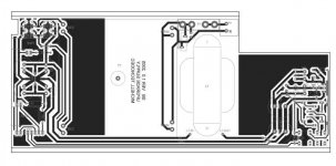
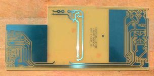
From the PCB image that I got, the IC used is made but Intersil, the part number is DAJ140E or CKJ140E. I was not able to find any information on the is part number. Maybe it is a standard part renamed for the NC customer and or come directly from asia.
Any clue what is this IC?
Thanks...
Any clue what is this IC?
Thanks...
There was once a thread dealing with never connected supply: http://www.diyaudio.com/forums/showthread.php?s=&threadid=29316&perpage=20&highlight=&pagenumber=1
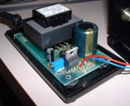
I got my table today, and the first thing I did was to open the standard power supply. It is a pretty standard LM317 9V voltage regulated supply, see image. The only thing special about it is the small DIN connector to connect the table's motor.
The supply voltages are: Transfo out 12Vac, 14.8Vdc no load, 9.7Vdc output voltage.
From the image that I got of the HR supply, it is a Never-Connected supply section supplying exactly the same LM317 regulated circuit as the original one. Not very sophisticated indeed. There is certainly place for improvement.
I'll try the suggestion of the OPA548.
My first prototype will be:
EMI Filter AC socket, Toroidal transfo, Schottky rectifier, C-R-C filter with Panasonic FC caps, LT1085 Low-Dropout adjustable regulator with a switch for 331/3 and 45 speed, OPA548 back EMF DC motor speed regulation. I'll include 2 pots to fine tune the 2 speeds.
Should be better than the stock supply
Attachments
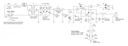
I tested the complet Turntable and Supply combo and the motor using an external power supply. I'll be able to have a 45rpm mode easily. The results are:
Transfo out 12Vac (50-70VA)
Volt before reg:
14.6V, nothing connected
14.4V, Motor, no load, motor current: 7.5ma
14.1V, Motor on load (with turntable), motor current: 20ma
Motor DC Resistance= 23.2 ohms
Needed DC output Voltages:
33rpm = 9,72V, adj. range +/-0.6V (for speed adj.)
45rpm = 13.20V, adj. range +/- 1V
Here my first version of the upgrade supply:
-EMI filter at the AC input
-50VA low leakage transfo
-Schottky rectifiers with snubber
-C-L-C Filter with Panasonic FC Caps
-Low Drop-out Regulator
-Dual speeds selector and speed fine adjustment multi-turn pots.
It was difficult to find the 3 pins connector mini DIN that Michell uses on its power supply. I found it!
It is made by Switchcraft. It is a Tini Q-G Connector, 3 pins, model TB3M, panel Mount.
Attachments
- Status
- This old topic is closed. If you want to reopen this topic, contact a moderator using the "Report Post" button.
- Home
- Source & Line
- Analogue Source
- Never Connected HR Supply circuit