Phonoclone no. 4
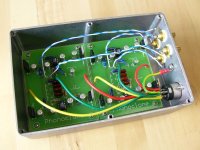
This is the fourth phonoclone I've put together, the last three of which have been using the PCB. Of the three that I've sat down and listened to, this is the most neutral. Its a little on the soft side, but at least it doesnt have the slightly intrusive treble of the original prototype. I put this down mainly to the filter caps, which were all low impedance types (ELNA and Panasonic) on the protoype, and regular Nippon Chemicon KMGs or equivalent on the later versions. The mica RIAA caps, for as far as I can tell, are sonically transparent ... I cant hear them at any rate. The bulk of the resistors are Riken ohm, with a couple of Panasonic carbon films in the RIAA since I cant get Rikens in these values, and a good old Allen Bradley for R8.
I recycled the old VSPS case (Hammond 1590D) and just managed to squeeze the two PC boards in there. Stuffing the board and hooking it up took less than 2 hours.
/R
Attachments
Richard
Many thanks for this great and very simple circuit!
I made one amp for me last week, for my DL103. This couple together really starts singing! It beats my formerly NAD PP2 without any discussion.
My amp is based on two OPA2227. No resistors between +input and ground. External, filtered, regulated and switchable PSU. Ferrite Beads direct before the bypass caps to filter any RC.
I prefer some voltage about 10V, concerning noise / sound.
Apropos noise: 10cm nearby my >95dB/W speakers, there is some very slight noise. No hum, when the psu is about 30cm away from the amp.
I am excited, now for more than 4 days listening to the amp.
Franz
Attachments
Sound
Richard,
I take this to mean that you prefer the sound using standard type caps. Is it more relaxed than the more expensive types?
George
rjm said:This is the fourth phonoclone I've put together, the last three of which have been using the PCB. Of the three that I've sat down and listened to, this is the most neutral. Its a little on the soft side, but at least it doesnt have the slightly intrusive treble of the original prototype. I put this down mainly to the filter caps, which were all low impedance types (ELNA and Panasonic) on the protoype, and regular Nippon Chemicon KMGs or equivalent on the later versions. The mica RIAA caps, for as far as I can tell, are sonically transparent ... I cant hear them at any rate. The bulk of the resistors are Riken ohm, with a couple of Panasonic carbon films in the RIAA since I cant get Rikens in these values, and a good old Allen Bradley for R8.
I recycled the old VSPS case (Hammond 1590D) and just managed to squeeze the two PC boards in there. Stuffing the board and hooking it up took less than 2 hours.
/R
Richard,
I take this to mean that you prefer the sound using standard type caps. Is it more relaxed than the more expensive types?
George
My hypothesis is that a low ESR cap right after the voltage regulator causes a certain amount of stress, hardening the sound.
I've been kindly given a set of Rubycon ZAs so I will try to get around to a definitive test, until then though its no more than a hunch.
/R
P.S. Speaking of tests, using some of the equipment at work I will try to at least put PC no4 through some basic tests: measurements of the frequency response and noise spectrum are planned.
P.P.S. Franz, when I get the chance I'll replace the 7x12s with 8 or 9 V versions and see if I can get an improvement. I just cant figure out why this should happen...
P.P.S. Franz, when I get the chance I'll replace the 7x12s with 8 or 9 V versions and see if I can get an improvement. I just cant figure out why this should happen...
I think it is a matter to optimize between headroom and noise. The higher the voltage, the higher the headroom but the same time noise is increasing eg. the S/N ratio is getting worse.
So, it could be an advantage to drive the first stage by a much lower voltage than the second stage. Maybe 5-6V for the first stage, 10-12 V for the second stage.
I cannot test it, as I used dual opamps

Do you still use LM7xnn? Aren't they to noisy? I prefer LM317/337.
Franz
I dont follow why the output noise of the op-amp should increase with the supply voltage. What is the rationale behind that?
I'm still using my humble 7812s. I've got a lot of mileage from these chips and I'm still interested in seeing just how far I can carry them up the hifi totem pole.
-rjm
I'm still using my humble 7812s. I've got a lot of mileage from these chips and I'm still interested in seeing just how far I can carry them up the hifi totem pole.
-rjm
Maybe it's more of the noise of the regulator?
LM317/337 RMS Output Noise is 0.003% of Vout (National Semiconductor datasheet). So as you increase the voltage you also increase the noise.
Fixed voltage regs output noise from NJR datasheets:
NJM7808 = 55uV
NJM7809 = 60uV
NJM7812 = 75uV
NJM7815 = 90uV
LM317/337 RMS Output Noise is 0.003% of Vout (National Semiconductor datasheet). So as you increase the voltage you also increase the noise.
Fixed voltage regs output noise from NJR datasheets:
NJM7808 = 55uV
NJM7809 = 60uV
NJM7812 = 75uV
NJM7815 = 90uV
Some say that a low esr cap after regulator is not a good thing. Here's one:
Jocko Homo said:All of those 3-terminal jobs have a feedback loop, and just throwing any old cap......especially with low ESR is asking for problems. It affects phase margin, and can easily make an oscillator. As you have found out.
Those of you with access to a spectrum analyzer.....here's what you do.
Look at the noise vs frequency with several different value and types of caps. You will see how the noise will peak at some frequency if you pick the wrong one.
If you don' t have an analyzer, but do have a 'scope and a square wave source.............drive the output with the square wave, and see if it rings. If it rings a lot, you have stabilty problems
Jocko
I dont follow why the output noise of the op-amp should increase with the supply voltage. What is the rationale behind that?
I should have write: "imho"

It was just a hypothesis of me, not beeing an electronic engineer. Maybe I was wrong?
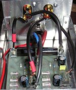
In the meantime I could buy very cheap two 15V military batteries and I just tested my amp with it.
The result: the (very little) noise is in fact induced and amplified as soon as I connect the TT to the input.
I do not remark any difference between the battery operated amp or LM317/337 based psu (at the same voltage).
Here a picture of the battery setup.
Franz
Attachments
Third option
A couple amplifiers I built lately use a dropping resistor, zener to ground, and a bypass pass cap to make a simple regulators for the input stage.
I do not have a scope, but people who do claim this is a cleaner supply than a three pin reg. Whether 78/79XX or 317/337.
I built a phonoclone last night, need to build the boxes to check. I used LM320/340. From specs this is inbetween the LM78/79 and the LM317/337.
If I hear some hash, may bypass the regs and install the zener circuit. The available current is adjustable, what is max current pull for the phonoclone?
George
Figure on 10mA per channel for the phonoclone circuit, 20mA per channel including the three terminal regulators.
A couple of people have now reported that the output noise did not change significantly when they swapped the linear regulated supply for batteries. Yet others have clearly heard a difference between 78xx and 317 regulators. That's hard to reconcile. The first observation indicates that the output noise is mainly generated by the phonoclone circuit not the power supply, the second would appear to confirm the opposite.
A very rough calculation would indicate that the voltage noise of the input op-amp should dominate the noise spectrum at least at low to moderate frequencies, while power supply noise would start to become important at high frequency, possibly well above the audio band.
Thus, although the audible noise background may remain the same the sound may still improve as changes are made to the power supply affacting the amount of HF (and RF) noise being injected into the circuit.
/R
A couple of people have now reported that the output noise did not change significantly when they swapped the linear regulated supply for batteries.
Again: in my case, the amp is absolutely silent, with open or shorted inputs, with psu or battery.
But some (very very little) noise is injected in my case as soon as the turntable is attached. So, I will have to investigate what I can tweak on the turntable.
In fact, the noise is absolutely no problem: with my nearby 100dB/W setup, I am just listening the noise when I have very high volume level, my ears 10cm nearby the speaker and no disc running.
Franz
With the input open circuit, the gain of the phonoclone is much lower than with a cartridge connected. That's why the noise gets louder - nothing to do with your turntable.
You can double-check this by connecting a resistor instead of the cartridge at the input.
Since the cartridge impedance or this dummy load sets the gain of the first stage, and thus determines the output noise to a great extent, you must have at least one of these in place before you measure anything.
Richard
I figured I'd upload the frequency reponse (deviation from RIAA) to the forum, for posterity.
cuz its pretty good.")
Its satisfying to know at last that the calculations actually do match reality. The .2dB bump in the midbass is the result of a couple of the RIAA components being about 1% off the target value.
/R
cuz its pretty good.
Its satisfying to know at last that the calculations actually do match reality. The .2dB bump in the midbass is the result of a couple of the RIAA components being about 1% off the target value.
/R
Attachments
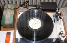
My vsps in the making..the transformers will be an alternative output..I am curious to compare them with the BG's
An externally hosted image should be here but it was not working when we last tested it.
Output Iron
I hope to drill the cases tonight to build mine. Let me know how iron works instead of the caps. Thought of this myself, just was unsure of how much offset there is. Using a cap with the transformer defeats the purpose.
There is a new pair of S & B 410A in my closet. Figured they would come in handy someday. They can deal with a couple mv offset. The input resistance is 38 ohms.
George
Will do.Let me know how iron works instead of the caps.
Phonoclone PCB grounding issue
Its come to my attention that the phonoclone PCB has a minor problem with the ground layout. Before everyone gets excited, please remember:
1. This does not affect the VSPS at all.
2. This does not affect the Phonoclone either unless you use an uregulated power supply.
Ok, the problem is the length of ground trace between the regulator ground pin and COM that is shared by the ground of the filter capacitors C8-11. The ripple currents (about 100mA peak) going though each trace coupled with the rather high resistance of the PCB traces induces a voltage spike on the regulator gound pin that of course floats the regulator output up accordingly. In other words, extra ripple is added to the op-amp's power pins, and find its way to the output.
This is explained in more detail here.
The solution is to rewire the ground leads of the filter capacitors C8-C11 directly to COM, as shown in the photo. Or switch and use a regulated power supply.
Making the mod did improve the sound, in my case.
/R
Attachments
![pc3m2_a[1].jpg](/community/data/attachments/37/37901-201b9a8d040eff701df4038942a6338f.jpg)
- Home
- Source & Line
- Analogue Source
- The Phonoclone and VSPS PCB Help Desk