Phonoclone 4 New Build - AT OC9/II question
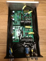
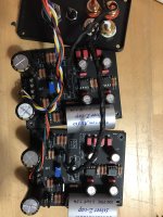
I originally built a Phonoclone 4 from the early 4.4 green boards Richard sent me") thanks!! - picture 1
thanks!! - picture 1
It was built in a little haste but sounded fine, however it had a little pick up from, I assume, RFI?, radio stations etc.
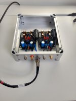
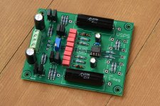
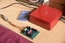
So I built a new version with recent 4.6 boards, taking a bit more time and using a larger case to allow the power supply and in/out cables to have shorter access paths - picture 2 .
Anyway it worked as the new version is much quieter, just some hiss (at high volume levels - but outside real world listening levels - at least in my house)
The positive news for me was, when out of curiosity, I swapped the original board with the new one it too was quieter - so I believe by wiring tangle was the culprit.
If your still with me - sorry its a bit long winded!
I do have a problem though.
I switched cartridges during this period and replaced my long standing Dynavector DV17DII with an Audio Technical oc9/II.
I get random volume drop outs on one channel - one channel reduces to very low volume - stopping and playing again seems to fix it. It appears to happen on both phonoclones.
I've yet to confirm if its a problem on a 'normal' phono stage - but will have to check this out to try and pin point the issue. Phonostage or cartridge?
I'm running the Phonoclone with pretty high gain - but I was always happy with what I heard - but was wondering if too high a gain in the phone stage could cause this type of issue - I know the Audio Technica has split coils - maybe it is affected more than the Dynavector?
Any views would be welcome.
Robert
I originally built a Phonoclone 4 from the early 4.4 green boards Richard sent me
thanks!! - picture 1It was built in a little haste but sounded fine, however it had a little pick up from, I assume, RFI?, radio stations etc.
So I built a new version with recent 4.6 boards, taking a bit more time and using a larger case to allow the power supply and in/out cables to have shorter access paths - picture 2 .
Anyway it worked as the new version is much quieter, just some hiss (at high volume levels - but outside real world listening levels - at least in my house
)The positive news for me was, when out of curiosity, I swapped the original board with the new one it too was quieter - so I believe by wiring tangle was the culprit.
If your still with me
- sorry its a bit long winded!I do have a problem though.
I switched cartridges during this period and replaced my long standing Dynavector DV17DII with an Audio Technical oc9/II.
I get random volume drop outs on one channel - one channel reduces to very low volume - stopping and playing again seems to fix it. It appears to happen on both phonoclones.
I've yet to confirm if its a problem on a 'normal' phono stage - but will have to check this out to try and pin point the issue. Phonostage or cartridge?
I'm running the Phonoclone with pretty high gain - but I was always happy with what I heard - but was wondering if too high a gain in the phone stage could cause this type of issue - I know the Audio Technica has split coils - maybe it is affected more than the Dynavector?
Any views would be welcome.
Robert
Attachments
@gtose
Thanks for the update and I'm looking forward to hearing your thoughts once you get it built. (looks great btw!)
@Naimart
I suspect the high gain is causing the DC output offset to occasionally push the output into the rails. For the Audio Technica, R2 should be about 150 ohms.
Maybe the op amp IC is a little wonky also, with unusually high DC offset. There is naturally some variation so it's not surprising that you see it in one channel only. Lowering the gain should fix things, that's anyway the first thing to try.
/R
I've been trying to find how to wire the toroidal transformer up to the power board for a while now and haven't found it yet. I've had everything but that, the switch, the fuse and the box done for a while now. Could you please advise me on how to connect the power. I've got the vsps.
Thank you for your time.
Thank you for your time.
You could have just asked right away!
The reason it's not given is because the connections depend on the transformer you use, and the diode configuration.
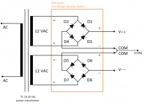
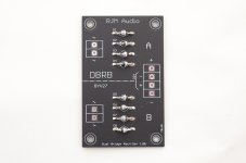
If you have the DBRB, or are using two bridge rectifiers or the discrete equivalent, it connects as per the diagram below. One secondary winding connects to the pair of ~ terminals on one bridge, the other secondary winding connects to the ~ terminals of the other bridge.
If you using just one bridge, please follow the directions provided by the transformer manufacturer to connect the secondary windings in series and connect the now center tapped secondary to a single bridge rectifier as per the standard textbook full wave bridge rectifier configuration. COM in this instance connects to the center tap directly.
See also the construction guide and DBRB bom file.
The reason it's not given is because the connections depend on the transformer you use, and the diode configuration.
If you have the DBRB, or are using two bridge rectifiers or the discrete equivalent, it connects as per the diagram below. One secondary winding connects to the pair of ~ terminals on one bridge, the other secondary winding connects to the ~ terminals of the other bridge.
If you using just one bridge, please follow the directions provided by the transformer manufacturer to connect the secondary windings in series and connect the now center tapped secondary to a single bridge rectifier as per the standard textbook full wave bridge rectifier configuration. COM in this instance connects to the center tap directly.
See also the construction guide and DBRB bom file.
Attachments
I'm sorry but I don't understand what most of that means.
This is the setup you sent me (Shared album - Ben O'Brien - Google Photos) Here are my questions.
I assume the clip side is ac. Which wires go to hot and cold and are those clips for some plug systems?
I assume the other side is for the board. Does it matter which side of the board each wire goes to?
Thank you for your time.
Richard. Looking at your blog, I've found someone who has done a review of VSPS400.
I see that there are ground connections on several sides, which you do not advise.
I have followed the advice of earthing only in the screw where it joins the turntable land, and yet there remains a slight humm that is perceived in music and convoluted in half.
Will I try to do it like this in this photo?
Greetings.
Review: RJM Audio VSPS 400 Phono Stage | Wall of Sound | Audio and Music Reviews
Here are my questions.
I assume the clip side is ac. Which wires go to hot and cold and are those clips for some plug systems?
I assume the other side is for the board. Does it matter which side of the board each wire goes to?
Thank you for your time.
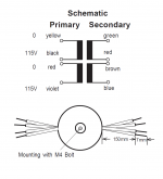
The transformer is Talema Standard Mini" Series Toroidal Transformers model 62062, 25VA, with two 12 V secondaries. (you can confirm is you slip off the copper/mu metal band from the transformer body)
The wire color assignment is found on the Talema website / catalog, reproduced below.
The wires with the clips go to the rectifiers. green and red go to one set of "~" pads on the DBRB, brown and blue go to the other set of "~" pads. Which winding goes to A or B does not matter, nor does it matter which pad of A, for example, the red or green goes to specifically. The four output pads + - + - connect to the VSPS etc boards as shown in the diagram.
The wires with the yellow cladding go to the AC. Since you are in Canada, your AC connects to the primaries in parallel. violet/black primaries to the black (live) AC wire and red/yellow primaries to white (neutral).
You can actually figure this all out without even needing the datasheet, just using a DVM and measure the resistance between different wires. You will automatically detect four pairs of wires with finite resistance, which gives you your four windings, two of which have relatively low resistance, which are the secondaries, and two which have relatively high resistance, which is the primaries. The only necessary information you would be missing in that instance is the phase of the primaries.
Attachments

Last edited:
Hi Richard
I just finished building PhonoClone 4 and everything went well except for a couple of strange issues related to some random noises.
I'm getting popping and buzzing noise that happens randomly. Popping noise sound like a pop in the vinyl, but it happens when nothing is playing. It's not very loud but I can see the woofer to move. Another noise is the buzzing, it's not persistent, last for a about a sec then disappears. It's much louder than the music though.
PSU with rectifiers board in a separated aluminum enclosure, and it doesn't makes any difference if I'm using single or dual transformer/rectifiers boards. PSU and enclosure is grounded to earth, PhonoClone is grounded to the grounding points on the board.
Any suggestion on where should I start to troubleshoot these issues?
Thanks
S.
Last edited:
@gtose
Thanks for the update and I'm looking forward to hearing your thoughts once you get it built. (looks great btw!)
@Naimart
I suspect the high gain is causing the DC output offset to occasionally push the output into the rails. For the Audio Technica, R2 should be about 150 ohms.
Maybe the op amp IC is a little wonky also, with unusually high DC offset. There is naturally some variation so it's not surprising that you see it in one channel only. Lowering the gain should fix things, that's anyway the first thing to try.
/R
Thanks Richard.
I reduced the gain and so far no repeat of the problem.
I'm getting popping and buzzing noise that happens randomly. Popping noise sound like a pop in the vinyl, but it happens when nothing is playing. It's not very loud but I can see the woofer to move. Another noise is the buzzing, it's not persistent, last for a about a sec then disappears. It's much louder than the music though.
That's an odd phenomena, I haven't come across it before. I tend to suspect some sort of instability or fault in the S-Reg part of the circuit. Do the output voltages trim nicely to equal? Are they stable?
PSU with rectifiers board in a separated aluminum enclosure, and it doesn't makes any difference if I'm using single or dual transformer/rectifiers boards. PSU and enclosure is grounded to earth, PhonoClone is grounded to the grounding points on the board.
It's unclear which enclosure you meant, but the phonoclone box should not normally be connected to earth directly. The ground lug connects to the turntable only. The power supply box should be connected to the AC line earth, but the COM (power supply ground) does not connect to the power supply box. See the guide for details.
So the first thing is to check the voltages V++, V+, V-, and V--. Also check the output offset voltage on pin 6 of the op amps. Second thing is to disconnect one channel and check each channel individually.
Probably best to contact me by email for troubleshooting this, I have a feeling it's going to be one of those extended jobs.
Thanks Richard, my email to you was blocked for some reason.
I did some tested with DVM, V—/V++ is measured around 16.8v, V-/V+ is closely matched to around 12.6V. Both readings seems to be stable as readings only vary ~0.1-0.2v.
I installed PSU and PC4 into two Hammond aluminum enclosures. PSU enclosure is grounded to earth and I also found TT grounding work better (less hum)when connected to the same grounding post. COM is not connected to the enclosure.
As I’ve mentioned about the random buzzing and popping noises. I don’t get the noise if there’s nothing connected to input. The buzzing sounds like the 120hz hum and only happens intermittently. Buzzing volume increases gradually as it occurs then die down quickly, all within about a sec. Popping usually happens about 5 secs before the buzzing occurs.
I’m suspecting C4/C5, transistors (I’m using BD135G/BD136G by ON). What do you think?
The voltages are fine, so I tend to suspect outside interference - RFI - is the root of the problem.
I'm reminded that I did experience intermittent buzzing once, some years ago. I traced it to the wifi AP/router which was on the same circuit as the stereo.
Wifi, routers, cell towers, wireless/cordless appliances can be suspect. Anything with a motor.
I suggest a two pronged attack, 1. is to find and hopefully remove the source of the interference, while 2. applying various anti-RFI tricks to the phonoclone itself.
I'd try perhaps switching opamps from OPA27 to OPA134, adding a 100 pF ceramic cap between pin 2 and 3 or the input op amp, ferrite beads, RFI filters on the AC line, etc.
Can't see why you couldn't email me, as we've communicated earlier. I'll ping you by email, you can try replying to that.
I'm reminded that I did experience intermittent buzzing once, some years ago. I traced it to the wifi AP/router which was on the same circuit as the stereo.
Yes. Or a computer next to the system. I was using a mac mini as a digital music server next to the audio system and would get occasional odd noises, usually quite short like has been mentioned. The computer was checking either for updates or making regular connections for any number of reasons over the wifi network. I moved it another foot or two away and the problem stopped (or got so quiet I couldn't hear it any more).
The voltages are fine, so I tend to suspect outside interference - RFI - is the root of the problem.
I'm reminded that I did experience intermittent buzzing once, some years ago. I traced it to the wifi AP/router which was on the same circuit as the stereo.
Wifi, routers, cell towers, wireless/cordless appliances can be suspect. Anything with a motor.
I suggest a two pronged attack, 1. is to find and hopefully remove the source of the interference, while 2. applying various anti-RFI tricks to the phonoclone itself.
I'd try perhaps switching opamps from OPA27 to OPA134, adding a 100 pF ceramic cap between pin 2 and 3 or the input op amp, ferrite beads, RFI filters on the AC line, etc.
Can't see why you couldn't email me, as we've communicated earlier. I'll ping you by email, you can try replying to that.
Thank you Richard. I indeed received your email and had to reply with a different email account, otherwise my email will be rejected due to "the message content violated service terms and conditions".
I had the chance to record the noise and uploaded here:
Vocaroo | Voice message
So I have tried following and the noise still persists:
1. Installed Delta EMI filter IEC socket.
2. replaced input/output signal cable with shielded cable.
3. Installed PC4 board into an extruded aluminum enclosure and placed into another heavy duty extruded aluminum enclosure, the thinnest board is 3mm.
4. Installed copper foil film to the inside of the enclosures and grounded to earth (also tested without ground).
5. Also tried to wrapped in aluminum foil.
6. Switched off everything, I mean EVERYTHING even the fridge.
7. Tested each board separately and no difference.
8. Tested interconnection including Van Den Hul The Integration, The Bay C4, QED Reference Audio 40.
9. I don't have OPA134, however I tested with LME49710. It's got some other issues but the noise is still present.
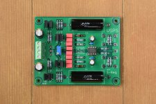
I also attached the picture of my PC4 boards, maybe it will give you some idea.
S.
Attachments
Last edited:
Everything looks nicely put together, but I would not bundle the input and output signals together like that, it can cause positive feedback and interference.
Given that the noise survives all your attempts at shielding and no local sources are apparent, but that you are experiencing different issues when you change op amps, I tend to suspect a configuration error.
Try soldering a 100 pF *ceramic* capacitor between the + and - inputs of the input op amp, IC1. As well as separating the input and output cables so they are at least a few cm apart, lower the gain of the phonoclone by reducing the value of R2 (solder an additional resistor in parallel to what you have, so it's easy to reverse the change.)
re. the noise, it sounds like oscillation to me, though I suppose it could be a RFI burst from a ham radio or cell phone transmitter or the like.
Last edited:
VSPS 6.0b bench notes
I'm using 6.81k in the S-Reg, which lowers the V+ to 8.5 V. 22.1 ohm emitter resistors.
The source current is 26 mA, the shunt is 15 mA. That means the op amp, OPA2134, draws 10 mA idle, leaving a good 5-8 mA of headroom in the S-Reg to meet the demands of the load.
This prototype is available by the way. I just built it to check it all works. As a 40 dB MM phono stage I have no use for it since I only have the DL103 cart at home. Price is $40, inc. shipping, but the buyer is expected to test and report back on the sonics, preferably someone who already has a VSPS or Emerald.
Attachments
Hi Steven,
You told me earlier you were using a DL-103R. R1 should be about 15 ohms, R2 should be about 332 ohms. Is that your setup currently?
There's one other thing, I note you've changed the bypass caps C10-13 from ceramics to film. I've never tried operating the phonoclone with film bypass caps, but ceramics or tantalum are typically recommended by IC manufacturer datasheets.
Please provide photos of the phonoclone and power supply cases.
That you had issues also with the LME49710, again, suggests the set up is wrong somehow. Either the grounding or the gain. Please measure the output DC offset at pin 6 of IC2. I need you to do this with the cartridged plugged in, so please be careful.
Richard
Hi Richard
Yes I’m using 103R, my R1 is 14.3R and R2 was 348R. However that didn’t help with the noise issue and gain was lower than the phono pre PC4 replaced with. Currently R1 is the same and R2 is about 570R I believe, gain is about 63-64db according to the calculator in BOM.
I just removed C10-13 and nothing has changed (w/OP27).
I will try to measure the offset voltage and report back.
Thanks again for your help.
S.
- Home
- Source & Line
- Analogue Source
- The Phonoclone and VSPS PCB Help Desk