That's the first time I've ever heard of one of my boards which was working stop working. With 9 V on all op amps (correct!), and no output from either board, I suspect everything is fine and it's something very simple ... (was your amplifier turned on? Preamp set to the right inputs? when you did the repair did you connect IN+ and IN- correctly and not backwards? input RCA connected to output by mistake??)
Still, you suspect a bad connection can double check continuity (zero ohms) between all the grounds (COM, IN-, OUT-, GND)
All I did was reconnect the power ground wire back to one board. The PS is fine. The output has cables hard wired and input sockets are good.
Looks like it has destroyed my old AT F5 MC cartridge. Luckily I wasn't using my OC9.
Tested the F5 with my trusty adcom preamp and no output either. I'm not risking the OC9 till I am sure it's working. I tried the dl103r (with one remaining functioning channel) with the adcom and it worked on one channel as expected. I have had this phonoclone for quite a few years now with no problems. I had been trying a new TT and shuffling phono stages around the house. Might have dropped it once as well.
Off to bed to cry myself to sleep.
Keva
I understand well?. So the electrolytes can be generic or have you wanted to tell me that the Nichicon FG or the UKZ are not advisable ?.
With respect to the resistors. Dale 1% resistors it well ?.
Or it is recommended better.
Excuse the insistence, but I want the VSPS400 to be better than the already excellent VSPS300.
With respect to the resistors. Dale 1% resistors it well ?.
Or it is recommended better.
Excuse the insistence, but I want the VSPS400 to be better than the already excellent VSPS300.
All I did was reconnect the power ground wire back to one board.
While the boards were powered up. With the cartridge attached. That's a big no-no. Never, ever poke around under those conditions. Since voltage is a difference between two potentials, COM is as dangerous as V++ and with the cartridge connected to COM on one hand, and the virtual ground of the op amp on the other, it's not too difficult to imagine the cart saw a few volts.
If it makes you feel any better, your cart was probably already dead by the time you went in there. It was the act of COM disconnecting rather than connecting it back that probably fried it.
Note from this point of view COM (power supply return) is dangerous, while GND (chassis connection) is not.
@gigigirl
No, this has nothing to do with the chassis ground connection to the TT or anything like that, but rather the connection, ultimately, between the cartridge and the power supply. This is not a user-adjustable parameter.
@all
I've been trying to simulate the failure in LTSpice, but while I've learnt a couple of things from it I can't seem to be able to reproduce a catastrophic failure sufficient to melt the cartridge. I admit I don't know how much current an MC cart can take before failing, however. As far as I can see running with COM disconnected from the board will cause excessive hum/noise but no produce no significant voltage offset on the cartridge.
If, re-connecting the ground wire back to the board, while live, it happened to touch V++ or V--, well, sure ... that's instant death for the F5 ... but COM by itself can be disconnected or reconnected and this by itself should not damage anything. In that my gut feeling and LTSpice are in agreement, but real world I haven't done the experiment to check so I can't be sure.
Kevan, do you have one phonoclone channel working or both? If your DL103 only has one channel, you can simply connect the working one to the Phonoclone's input right and left in turn, to verify. If the cartridge took enough current to burn, that current must have come out of the op amp input, which likely means IC1 has fried also. Certainly, if you have no sound from one channel, replacing IC1 would be the first thing to try.
@Jose
I don't mean to sound unhelpful, but on the subject of parts: I specify the values, and a suggested BOM part model based on fitness-for-purpose and availability in the Mouser catalog. Barring some occasional and notable exceptions, I do not recommend brand X over brand Y based on which sounds better. On a personal level and speaking of my personal builds, I don't really care about such things. I'm a circuits guy, not a parts guy.
Sigh. Since you asked though:
Dale/Vishay 1% resistors are excellent and high quality. The cost at Mouser makes them hard to justify over the perfectly fine KOA Speer ones though.
Since I haven't used FG/KZ I cannot comment on whether they are good or better than anything else. I have used the lower grade and cheaper KW and FW exclusively for many years with no complaint or dissatisfaction. I expect the FG/KZ to be better - one would hope you get something - but in what way I cannot possibly say.
Mica are the cleanest and most transparent for the RIAA caps, but I have no problem recommending Wima FPK as a perfectly good substitute.
The only part where brand and cost seems to make a, to me, important difference is the coupling cap. My recommendation there is unchanged: use whatever you like and feel comfortable paying. Personally, I cycle around Multicap PPFXS, Mundorf Supreme, and Audyn KP Sn. I'm not prepared to say they are better or worse than anything else, only that I have used them and like them.
Last edited:
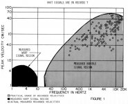
If you build phono stages, or even if you just play records, if you are into diyaudio this technical seminar from Shure is a must read.
Now armed with the knowledge that the maximum needle velocity is about 40 cm/s, let's go back and revisit, hopefully for the last time, the question of phono stage gain.
Nothing has really changed. The recommended gains are what they always were. What this will do however - let's hope - is give you a full appreciation for why the gains are set as they are.
Cartridge sensitivity is given as mV at 5 cm/s needle velocity. For simplicity let's make the absolute maximum needle velocity 50 cm/s, giving an even 20 dB difference between the rated output in mV and the maximum voltage that can come off the cartridge.
The design goal is that your phono stage should have enough headroom that even this maximum voltage does not result in clipping. To achieve this, either the voltage gain must be reduced, or the signal clipping voltage increased. The latter is obtained by increasing the voltage rails, or possibly moving to a high voltage circuit topology such as vacuum tubes.
Assuming your circuit can handle it without clipping, how do you figure out the the right gain to produce about the same output level as a CD player?
Well, what it is not is what most people here seem to figure it is, aka
gain (dB) = 20 log [ 1000 / cartridge sensitivity in mV ]
This gives 60 dB for 1 mV, and overestimates the gain needed by at least 10 dB.
It doesn't matter whether you estimate the line level as 0 dB, 3 dB, 2 V rms, 2 V p-p, these are all the wrong reference to use. A 1 mV sensitivity cart amped by 60 dB will not give you a signal the same level as your CD player, it will be much louder - and you will likely overload any op amp based phono stage while you are at it.
So what is the gain needed? Unfortunately it's not straightforward or obvious. If it was, people wouldn't get it so wrong all the time. The trick is solving the relationship between the 5 cm/s velocity reference and the -10 dB reference level for consumer line level audio. There is no direct link, it only depends on the conventions of the recording industry. To first approximation however, we can draw a 1:1 correspondence. So, a 5 cm/s 1 kHz sine wave pattern on an LP groove passed through a transducer and amplified to -10 dB should give the same level as a -10 dB 1 kHz sine wave recorded on a CD and played on a standard consumer CD player.
This gain should be regarded as the upper limit. There is no legitimate need to have the phono output level-matched to the CD output. If 6~10 dB lower gain gives better noise performance and better overhead protection, as it often does, then this is an advisable design decision to take.
The formula to calculate the maximum phono stage gain is,
gain (dB) = 20 * log ( 1000 * 0.316 / cartridge sensitivity in mV)
As discussed earlier, this must be refined by considerations such as the range of cartridge sensitivities the phono stage is designed to accept, and the circuit headroom, not just at the output but also in the interstage. Poor design decisions about where to implement the RIAA filter in multistage designs can reduce headroom drastically.
Using the Emerald as an example, configured as a 40 dB MM and with a 2 mV cartridge,
2 mV at 5 cm/s means we might expect 100 mV absolute peak output. This produces 10 V rms at the Emerald's output, clipping IC2 severely. At 34 dB on the other hand, clipping is avoided.
Mitigating this is the fact that, 1) as the diagram below shows, the maximum velocity is frequency dependent, and at 1 kHz something less than this maximum can be expected (the lower phono stage gain at high frequencies means there is no problem with clipping with 100 mV at 20 kHz, and that about 5 kHz is probably the worst case frequency range, and 2) the likelyhood of such high velocity ever being encountered is probably one instantaneous instant over 100 albums. Quite possibly much, much less. So its not really such a big deal.
Still all things considered, especially when noise considerations are brought to bear, there is absolutely no shame in setting your phono stage to the traditional 35/55 dB. In fact - considering that most modern audio systems are overly sensitive - I rather recommend it.
/RJM
PS. This belongs in my blog, but until diyaudio brings back posting ability I'm afraid these long-format screeds are going here.
Attachments
Last edited:
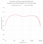
The Emerald can be configured for 35/55 with R3 = 100 ohms and R4 = 2210 ohms, both part of my standard toolbox resistor values.
As can be seen in the simulated response, lowering the MC gain brings the HF response back in line with the MM, and coupled with that is somewhat improved performance.
I may likely change the BOM to make those the default values.
As can be seen in the simulated response, lowering the MC gain brings the HF response back in line with the MM, and coupled with that is somewhat improved performance.
I may likely change the BOM to make those the default values.
Attachments
correction to post 3829
With 2 mV we can expect 20 mV at 50 cm/s not 100 mV. A better "worst case" scenario is a 7 mV cart, which means 70 mV cartridge output (-23 dB) at 50 cm/s.
Emerald, phonoclone, and VSPS are all designed such that the highest voltages at all audio frequencies are seen at the output so no need to worry about the interstage levels. Output clipping starts about 6-7 V rms, or 15 dB. That sets the maximum MM gain limited by a 7 mV cart at 15-(-23) = 38 dB. The same argument suggests 58 dB as the maximum gain given a 0.7 mV MC cartridge.
Any way you slice it, 40/60 dB is about the limit you would want an op amp phono stage before headroom starts to become a concern, unless you are sure to only use it with low output cartridges.
As a practical matter, these gains also return typical music signal levels. All it really shows is that increasing the phono stage gains beyond 40/60 will very quickly lead to trouble paired with high output carts. There is little reason to think that 40/60 is a problem. 35/55 just offers a proportionately larger cushion. From my point of view the advantages of 35/55 is more in the amount of feedback applied to the op amp at high gain, and resulting improvements in noise/distortion.
2 mV at 5 cm/s means we might expect 100 mV absolute peak output.
With 2 mV we can expect 20 mV at 50 cm/s not 100 mV. A better "worst case" scenario is a 7 mV cart, which means 70 mV cartridge output (-23 dB) at 50 cm/s.
Emerald, phonoclone, and VSPS are all designed such that the highest voltages at all audio frequencies are seen at the output so no need to worry about the interstage levels. Output clipping starts about 6-7 V rms, or 15 dB. That sets the maximum MM gain limited by a 7 mV cart at 15-(-23) = 38 dB. The same argument suggests 58 dB as the maximum gain given a 0.7 mV MC cartridge.
Any way you slice it, 40/60 dB is about the limit you would want an op amp phono stage before headroom starts to become a concern, unless you are sure to only use it with low output cartridges.
As a practical matter, these gains also return typical music signal levels. All it really shows is that increasing the phono stage gains beyond 40/60 will very quickly lead to trouble paired with high output carts. There is little reason to think that 40/60 is a problem. 35/55 just offers a proportionately larger cushion. From my point of view the advantages of 35/55 is more in the amount of feedback applied to the op amp at high gain, and resulting improvements in noise/distortion.
Last edited:
While the boards were powered up. With the cartridge attached. That's a big no-no. Never, ever poke around under those conditions. Since voltage is a difference between two potentials, COM is as dangerous as V++ and with the cartridge connected to COM on one hand, and the virtual ground of the op amp on the other, it's not too difficult to imagine the cart saw a few volts.
If it makes you feel any better, your cart was probably already dead by the time you went in there. It was the act of COM disconnecting rather than connecting it back that probably fried it.
Note from this point of view COM (power supply return) is dangerous, while GND (chassis connection) is not.
No. It was all disconnected and in a different room!!! Who would solder with power running through the wires?
My error was using stiff wire, probably too thick (18GA) and fitting it all into a case that was too small. i will use screw in terminals next time.
kevan
Hi Richard,
I am considering building a passive pre-amp (transformer or attenuator volume controlled - not sure which yet).
The source would be the VSPS or Emerald and the load a conventional transistor power amp (the Rega Maia to be specific). At some time in the future I may want to switch to a tube power amp.
Would there be any potential impedance matching issues? Thanks for any advice you may be able to give.
Regards, Dutch Keith
Who would solder with power running through the wires?
Well, I mean... I don't know, do I? You'd be surprised at some of the stuff I hear about. (...)
 Back to square one then I guess: I can't explain the sequence of events that led to the cartridge getting damaged. I don't even know if it happened before you repaired the connection, or afterwards. As you can imagine this bothers me as I like to have a grip on the safety envelopes. I've always considered the circuit quite robust to anything other than errors involving the V++ and V-- connections.
Hi Richard,
I am considering building a passive pre-amp (transformer or attenuator volume controlled - not sure which yet).
The source would be the VSPS or Emerald and the load a conventional transistor power amp (the Rega Maia to be specific). At some time in the future I may want to switch to a tube power amp.
Would there be any potential impedance matching issues? Thanks for any advice you may be able to give.
Regards, Dutch Keith
Whatever you have for a passive preamp should present an input impedance of 10 kohms or greater. That's the only consideration.
Though as the last couple of posts on the subject has shown, the gain lost by not having an active line stage cannot be made up for by increasing the phono stage gain to compensate, but rather that the downsteam system and listening environment allows for a lower front end signal level.
- Home
- Source & Line
- Analogue Source
- The Phonoclone and VSPS PCB Help Desk