I could reduce scatter and improve accuracy by using the scope's rms voltage measurement rather than the p-p values.
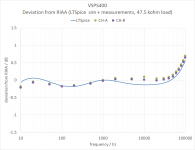
Formal simulated 1 kHz gain is 40.94 dB. Measured is 41.17 / 41.15 dB.
In terms of a specification, the circuit measures within +/- 0.15 dB of RIAA 20-20 kHz. Channel imbalance is negligible.
Jose: yes, leave C1 at 1 nF. Everything was fine all along, my measurement setup was inducing strange result.
Attachments
Last edited:
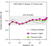
Same data, done up "brochure style".
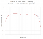
VSPS400e makes RIAA ±3% (±0.25 dB) between 10 Hz and 50 kHz.
I was using 2.5% Wima FPK caps in this build, and 1% resistors. This is "parts as received" - I did not match or select components to improve the result.
VSPS400e makes RIAA ±3% (±0.25 dB) between 10 Hz and 50 kHz.
I was using 2.5% Wima FPK caps in this build, and 1% resistors. This is "parts as received" - I did not match or select components to improve the result.
Attachments
Final word on this:
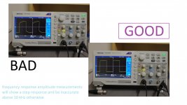
PRO TIP: Calibrate your oscilloscope probes regularly.
However, for measuring signal amplitudes at audio frequency it's best to avoid 10x probes altogether. The measurement accuracy starts to depend on the compensation effectiveness at frequencies above 10 kHz, right where you most want consistent and accurate measurement. Use regular coax cable instead and you avoid the whole problem entirely.
Attachments
Last edited:
some new stuff
This is my yearly "where are we going with RJM Audio" post. Since the blogs aren't up yet, and it mostly pertains to the phono stages, I'm dropping it here.
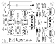
The Emerald phono stage is looking good. It replaces the VSPS400 and arguably the Phonoclone4, pending some critical listening tests.
The boards have been refined since the evaluation 10c. Primary change is to add support for Nichicon FG electrolytic capacitors, though some additional efforts on the silkscreen layer make the build more logical and hopefully easier to understand (i.e. less likely to mess up).
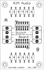
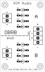
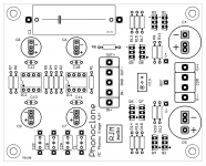
In addition - with the view to make the whole thing a "turnkey" project - two additional, optional boards are going to be linked with the phono stage. The first is the "Switchboard", which expands the cartridge loading options to up to six more resistors or capacitors, and combinations thereof. The second is the "DBRB", or Dual Bridge Rectifier Board. Nothing special with that, it's just a convenient holder for 8 BYV ultrafast recovery diodes for people who don't want to use chassis-mount bridges.
Comments and requests welcome. These are final-review stage, meaning they are ready for fabrication but I haven't sent them yet so I can still add small things.
This is my yearly "where are we going with RJM Audio" post. Since the blogs aren't up yet, and it mostly pertains to the phono stages, I'm dropping it here.
The Emerald phono stage is looking good. It replaces the VSPS400 and arguably the Phonoclone4, pending some critical listening tests.
The boards have been refined since the evaluation 10c. Primary change is to add support for Nichicon FG electrolytic capacitors, though some additional efforts on the silkscreen layer make the build more logical and hopefully easier to understand (i.e. less likely to mess up).
In addition - with the view to make the whole thing a "turnkey" project - two additional, optional boards are going to be linked with the phono stage. The first is the "Switchboard", which expands the cartridge loading options to up to six more resistors or capacitors, and combinations thereof. The second is the "DBRB", or Dual Bridge Rectifier Board. Nothing special with that, it's just a convenient holder for 8 BYV ultrafast recovery diodes for people who don't want to use chassis-mount bridges.
Comments and requests welcome. These are final-review stage, meaning they are ready for fabrication but I haven't sent them yet so I can still add small things.
Attachments
Last edited:
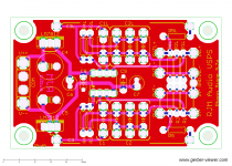
Stereo VSPS rev. 5.2a
Almost the same as the previous 5.1 update, but I fixed the board size to 80x50mm exact and standardized the mounting hole dimensions to metric likeh the rest of the recent boards.
Almost the same as the previous 5.1 update, but I fixed the board size to 80x50mm exact and standardized the mounting hole dimensions to metric likeh the rest of the recent boards.
Attachments
Stereo VSPS, Phonoclone, Emerald, Sapphire, S-Reg, and DBRB will be updated to the versions shown above soon. I've already placed the order for the Stereo VSPS, Phonoclone, Emerald, and DBRB boards.
Mainly because I wanted to order the Emerald, the rest were all minor revisions. The Stereo VSPS changes the RIAA to drop the 4th time constant, the new Phonoclone brings compatibility with larger capacitors. Otherwise it's just cosmetic changes from the previous versions.
BOM etc available from the web page.
I've attached the Emerald BOM here, though it's already uploaded to the website. There's a worksheet which lets you experiment with resistor values R1-5, for customized load and gain options.
Re B&O cartridges, I've got a couple of things to say on that and I'll have to be careful in my bullet point ordering so as not to derail the thread.
Okay.
1. To keep 47.5k load, JP1-1 is left open, while closing JP1-2 will increase the gain to 60 dB in stock configuration. The high gain setting would bring a 2.2 mV cartridge to 2.2 V, which is close to your stated goal. You can change R3 to 150 to reduce the high gain output to 52 dB, giving an output closer to 1 V and leaving the low gain setting unchanged, or you can change R4 to 150 ohms to increase the low gain setting to 52 dB, leaving the high gain about 60 dB.
Actually though, what you really want is 46 dB and an output level of about 300 mV.
.deep breath.
2. The sensitivity of a cartridge in mV does not follow the same standard as the line level output of a CD player. Multiplying a cartridge with an listed sensitivity of 1 mV to 1 V rms (0 dB) line level standard doesn't mean the sound level will be the same as a CD player. Consumer audio line level is closer to -10 dB, and 300 mV is closer to the number you want to "hit" when multiplying the cartridge sensitivity by the phono stage midband gain. The traditional phono stage gains of 36 dB MM and 56 dB MC give the correct output with "typical" cartridge sensitivity of 5 mV and 0.5 mV respectively. The B&O is only 6 dB lower than typical MM. In my experience it's not worth worrying about 6 dB one way or another in a phono stage. That level of difference is easily mopped up by your preamp's volume control. To the ear the difference in signal loudness is not especially great. Indeed that's the general thinking in preamp design: 36 dB covers 2.5-10 mV range of MM sensitivities, 56 dB covers 0.25-1 mV. B&O is just in the middle ground where, if these things bothered you, you might find yourself wanting about 46 dB. If you were building the Emerald specifically for this cart, maybe set it up to have "MM-LO" 36 dB and "MM-HI" 46 dB gain positions [R3 475 ohms, R4 1.5k]]. That would give 440 mV with your B&O and a similar output level with MM carts hovering around 5 mV. As a bonus, the MM-HI setting would also be good with high output MC which often hover around 1-2 mV output.
I'd also set R2 to 1k, so the loading options were 47k5 and 1k.
The more I think about what I wrote here, the more I think this (i.e. MMLO MMHI, 47k/1k) would be a pretty sweet setup for a high end MM phono stage.
Attachments
Last edited:
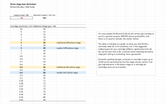
This hopefully gives a better idea of the numbers involved.
People do seem to want to overthink this, making a problem out of something which really isn't one. Just build your phono stage 40 dB (MM) and 60 dB (MC) ballpark figures, and you'll be good to go.
I recommend the vinyl engine cartridge database for lookup info.
As far as I can see only a few "problem" cartridges exist in the grey area around 1.0 mV lying about mid way between MM and MC centerpoints. Examples include the Benz Micro Glider, some of the high end Grados, and one or two models from Roksan and Van den Hul. A similar number of cartridges fall into the "ultra low output" class 0.10 mV and below, where a gain higher than 60 dB could be rationalized. Audio Note, some Denon, Benz again, and Fidelity Research. Taking the grand prize is the Ortofon MC 10 mkII at 0.024 mV and few similar 0.05 mV and below which would indeed require a special setup.
The difference in gain between traditional and modern circuits is a combination of average cartridges outputs getting smaller over the years, the increased availability of cheap op amps with low noise and high voltage gain, and the increase in standard line level outputs coinciding with the introduction of digital audio.
Attachments
Last edited:
Emerald BOM 1.0s2
cleaned up and expanded the BOM a little, no major changes or fixes
- default BOM electrolytic caps are now Nichicon Muse UKZ.
- default BOM R3,4 are 56.2R and 750R, so gain is 40/60 exactly rather than a more awkward but perfectly reasonable 39/59 dB obtained with 68.1R/1k. The reason I prefer the latter is they fall in my list of standard resistors I keep around in stock, but so many of the other resistors in this circuit need to be bought specially there's not really a big deal about adding a couple more.
- added some worksheets to explain the relationship between gain and cartridge sensitivity re. post 3815 above, for interests sake only.
- added workable alternative versions of the Emerald circuit: 40/50 dB, 50/60 dB, and 60/70 dB.
Attachments
Last edited:
Richard. I'm confusing. As I mentioned, I must buy the components to assemble the VSPS400 outdoors.
I want to assemble it with the best components, that's why I'm delaying in completing it.
But I see that you are assembling with electrolytic Nichicon Muse UKZ. Are they better than FG ?. What electrolytic would you recommend ?. For the RIAA capacitors I will use Cornell Dubilier 1%. It's okay?. Resistors DALE 1%. There are other recommendable ?.
regards
Hi RJM,
My second phonoclone3 has also stopped working. One channel died first which seemed to be caused by the ground cable on one board lifting off the solder. Looks like I wasn’t making good joints with my old 20w iron.
I connected the ground but now am getting nothing from either board. I am getting 9v across pins 3 and 7 of the first and second 8pin dip socket. Are there any other measurements I can do to check what is going on? I'm sure you have mentioned it somewhere in the thread but its hard to find.
I haven’t ordered the parts for the Emerald as yet but would like to get this one working as well.
Thanks,
Kffern
@Jose
My comments and notes about the Emerald circuit do not apply to the VSPS400, and vice versa. For the VSPS 400, please use the BOM or equivalent parts.
I do not in any case recommend FG or KZ or whatever, but since people want to use these "audio grade" electrolytic capacitors I have modified the latest boards (Emerald and Phonoclone) to make this possible.
I actually have ordered some FG and KZ from Mouser, and will see if I can imagine they improve the sound. They aren't very expensive, so its not a big deal either way.
@Kevan
That's the first time I've ever heard of one of my boards which was working stop working. With 9 V on all op amps (correct!), and no output from either board, I suspect everything is fine and it's something very simple ... (was your amplifier turned on? Preamp set to the right inputs? when you did the repair did you connect IN+ and IN- correctly and not backwards? input RCA connected to output by mistake??)
Still, you suspect a bad connection can double check continuity (zero ohms) between all the grounds (COM, IN-, OUT-, GND)
- Home
- Source & Line
- Analogue Source
- The Phonoclone and VSPS PCB Help Desk