I have posted this diode protection advice very many times in various Threads !I like that idea, AndrewT. I'll use it!
A few Memebrs have now incorporated it into their amplifier PCB layouts.
type Mains Bulb Tester into the Forum's "search" function.
diyaudio's search (dis)function didn't connect me to an actual description, but I infer it is a tungsten light bulb connected in series with the amplifier on the AC line. A short will drop all the voltage across the bulb, turning it on and limiting the current proportional to the wattage of the bulb.
Note to the younger kids: don't try this with a LED bulb...
Yes. That's it. But I particularly like Andrew's twist with a diode for reverse current.
Richard, can you give me/us a hint why you have chosen these specific parts in the BOM for the Phonoclone? Do f.e. the carbon resistors at the output have some significant influence about the sound in your opinion?
(I admit I have not read the whole thread...It must have been a topic before)
Klaus
(I admit I have not read the whole thread...It must have been a topic before)
Klaus
Yes, that's come up a few times before.
I don't dictate the type/brand of parts, as long as the value is right you can use whatever you want. The BOM is a guide, suggestions based on availability at Mouser.
I use carbon comp 47 ohm resistors for damping, and other places where I judge low inductance to be more important than low noise. Otherwise metal film ... though personally I don't have a problem with carbon film ie Takman or Riken Ohm.
A lot of the BOM values are chosen to keep to as small a set of standard parts as possible across all my projects, so as much as possible I don't have to keep stock of parts specifically for just one circuit.
R
Thanks for the answer.
One advantage of the Phonoclone is the possibility of variations , of parts and their quality etc. due to a very simple circuit. I have already bought (and collected...) several suitable parts to have a listen (styroflex vs. silver mica, carbon vs. metalfilm, and different opamps).
I, btw, have been using Rikens and even much more basic carbon resistors in many circuits with interesting results. You are right, sometimes noise is not the only criterium.
Not necessarily a PCB related question, as I'm making one of these on veroboard, but more an honestly confused query from someone who has never used an opamp before but can solder to a diagram!
I was showing the VSPS circuit and construction guide to my girlfriend's father, an engineer of 40 years experience, and his first reaction on seeing the recommendation for a 35VA transformer, or 100VA for improved quality was, (and I quote) "snake oil", although he admitted he can be dogmatic about these things! If I recall correctly, he argued that the power dissipation in the circuit should be the deciding factor in the transformer selection and that the circuit could run happily off something rather more thimble-sized with no effect on the quality.
He (and I) are interested to know what the rationale for this recommendation is in the construction guide kindly provided by RJM Audio. Oh, and many thanks for the circuit!
It's buried back in the thread, but a long discussion amounts to: several people tried it and agreed it does sound better.
Of course 25 or even 10 VA is sufficient.
Perhaps it's worth repeating: the VA rating is for an AC load. Rectification means the transformer is conducting high currents for very short pulses, which heats the transformer more than the same average current passed continuously. It also causes a relatively high frequency electromagnetic noise spike that, I can assure you, is far from harmless so far as getting into the output signal.
High end audio tends to use much higher filter capacitance than is normally considered reasonable, resulting in the current pulses being extremely high and extremely short. This stresses both the diodes and the transformer, and makes the noise spike more severe.
How the transformer reacts to this stress is going to be a function of its resistance and inductance etc., which vary with the VA and quality and type. This changes the shape of the ripple voltage, and the noise spike.
So while I can't say that a larger VA rating should necessarily be better, it seems entirely reasonable to expect that different transformers will be distinguished by audible differences in the output.
My pet theory is small transformers tend to ring on the noise spike, aggravating the effect, while larger ones tend to damp it out. No clue if this is correct or not. I should also say I am happy to use 25 or 50 VA transformers for even projects like my headphone amp where the current draw is much larger.
Finally, I recently discovered Triad VPM medical transformers with screen and shield are available at digikey and similar outlets. So today, I would change my recommendation from "bigger" to "better" and suggest everyone goes with the VPM if they want to upgrade their power supply.
Last edited:
Thank you Richard. I'm sorry to bring it up again - a search didn't register the previous discussion in this thread. I suppose when there are 339 pages that the DIYAudio search-o-tron 3000 can get confused. You must be proud of your creation.
He's just read your reply and while he can see where you're coming from, he still thinks it's unconvincing. As background he mentioned a set of amplifiers similar to audio circuits he built driving 89 wave generators in a tank during wave-power experiments. The power transistors were run straight from the rectifiers on a power supply built from a welding transformer and were able to reject the significant ripple with no effect on their instrument measurements. (Other parts were run on far more filtered supplies!) He can't see why when the current draw is so small, other than the initial charging of the capacitors, that there is any engineering reason for such an oversized transformer, and wonders if those who thought it sounded better made blind ABX tests.
This is well outside my expertise, so I'll leave it there to avoid getting into a third person flame war, unless I can persuade him to come to the keyboard!
I hope when I get the circuit built I can make some power supply experiments... If so, I'll report back.
Thanks again for making this circuit available - a real boon to have something so simple to use, especially when my rather more complicated valve stage has been in pieces for years for want of time...
Rest assured there is no engineering reason. All it amounts to is a suggestion based on an empirical observation, rationalized with some basic facts about how rectified power supplies work.
I'm generally pretty skeptical, but - well, it is what it is: diodes, capacitors, transformers can all change the sound. I'm not so convinced about power cords, cables, resistors, and vibration isolation and what not. I don't deny the possibility that they might, but personally I don't feel it makes enough of a difference to worry about much, if at all.
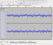
PS. attached is an example (not the VSPS) where transformer current pulse noise has coupled to the output signal. It's small, but yes, it influences the perceived clarity of the sound.
I'm generally pretty skeptical, but - well, it is what it is: diodes, capacitors, transformers can all change the sound. I'm not so convinced about power cords, cables, resistors, and vibration isolation and what not. I don't deny the possibility that they might, but personally I don't feel it makes enough of a difference to worry about much, if at all.
PS. attached is an example (not the VSPS) where transformer current pulse noise has coupled to the output signal. It's small, but yes, it influences the perceived clarity of the sound.
Attachments
Personally I find the suggestion that bits of paper in oil can do anything other than leak, or bits of wire wrapped around some iron can adjust an invisible force unfathomable enough, but it works. But yes, I draw the line at the more obvious fool-and-money items like cable lifters, oriented electrons and so forth...
It's when people start listening to components rather than music - I'm sure I've had more fun with a semi-stretched tape of a record I love, played on an amp I've fixed up on a student's budget than I would have done with an SACD on an expensive bought system!
Thank you for the graph. I'll have to do some 'scope experiments when I build the circuit - perhaps they'll help with the power supply filtering of my valve pre-amp! O, that pesky hum.
I have a question about R1 in the Phonoclone. It is said that it should have nearly the same value as the output impedance of the cartridge, but that it can be omitted. So I wonder what is the purpose of this resistor and what are the pros and cons of each solution (R1=cartridge impedance or R1=0).
A unique fumble...
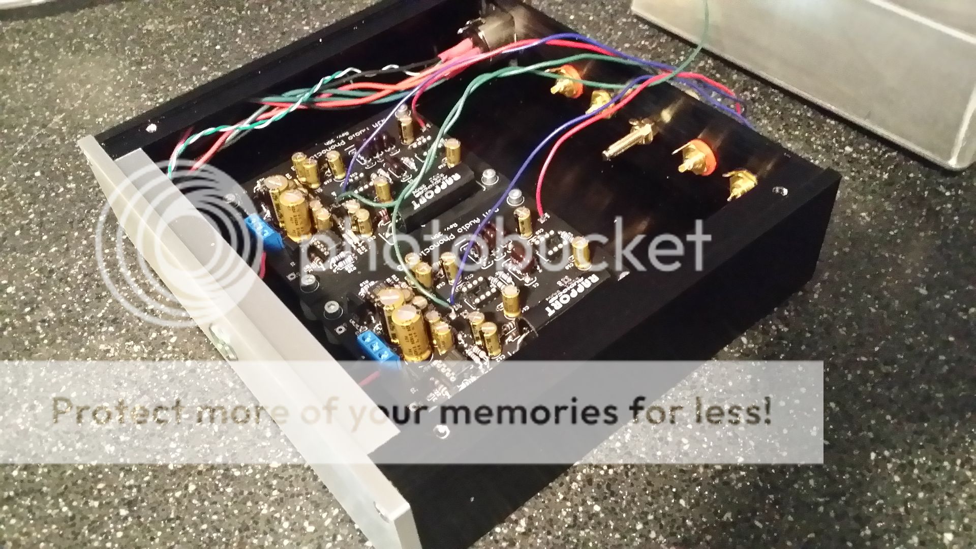
I should never have joked about the danger of turning me loose with a soldering iron. I managed to damage my Phonoclone 3 assembly.
Finished and tested power supply...all solid there. Completed boards, mounted them in enclosure and wired all but input/output cabling (in case it might be necessary to remove and repair during early testing).
I powered up the system and began making the RJM suggested preliminary voltage checks before installing the final 2 OP27 devices per board. Within a few seconds C4 (board A) bulged and popped, C4 (board B) bulged, but did not pop before I was able to power off.
Since those caps are on the -12V side, I checked the voltage at the pins of the XLR that powers the boards. Over 30 Volts on the -12V pin... ...looks like I blew it somewhere in the cable assembly. I've been too disgusted to take it apart to see just what I did. Replacing it with a standard XLR cable showed correct voltages (15V and change) and polarities at the proper pins.
Obviously, the C4 caps need to be replaced. What other components have I likely/possibly damaged? Should I order a few spare OPA27GP along with the caps, just in case?
On a positive note, the power LED on the enclosure did glow nicely...

I should never have joked about the danger of turning me loose with a soldering iron. I managed to damage my Phonoclone 3 assembly.
Finished and tested power supply...all solid there. Completed boards, mounted them in enclosure and wired all but input/output cabling (in case it might be necessary to remove and repair during early testing).
I powered up the system and began making the RJM suggested preliminary voltage checks before installing the final 2 OP27 devices per board. Within a few seconds C4 (board A) bulged and popped, C4 (board B) bulged, but did not pop before I was able to power off.
Since those caps are on the -12V side, I checked the voltage at the pins of the XLR that powers the boards. Over 30 Volts on the -12V pin...
...looks like I blew it somewhere in the cable assembly. I've been too disgusted to take it apart to see just what I did. Replacing it with a standard XLR cable showed correct voltages (15V and change) and polarities at the proper pins.Obviously, the C4 caps need to be replaced. What other components have I likely/possibly damaged? Should I order a few spare OPA27GP along with the caps, just in case?
On a positive note, the power LED on the enclosure did glow nicely...
I always assume, like Morgan Jones, that whatever I've made will explode or at least catch fire when turning on.
I have also made great XLR failures when the measurements say all is well, but one then realises that it's wired up back to front when viewed from the other side. In accordance with Sod's Law, after at least one component has gone, of course.
My grandfather, an electrical engineer, always consoles me with saying that 'if it works when you first turn it on, it means you haven't found what's wrong yet!'
I'd just replace the caps, use a mains bulb tester, make sure the PSU cable's correctly wired and try again. If it lights up, then make the effort of going through all the audio wiring.
So you'd be surprised how many people make this kind of mistake.
I'd hoped people would measure the voltages at the XLR connection before going on to hook up the boards to the V++ and V--, but ... it happens.
On previous experience usually you just have to replace the 1000 uF capacitors on the damaged side and things will work. In principle some 100 uF caps and the semiconductors could be damaged, but in practice they seem to come out ok.
On previous experience usually you just have to replace the 1000 uF capacitors on the damaged side and things will work. In principle some 100 uF caps and the semiconductors could be damaged, but in practice they seem to come out ok.
I replaced the 1000uF capacitors, checked the surrounding passive components, TRIPLE checked the power cabling and fired it up. Pin 4, IC1 reads -10 both boards...off to a good start. Pin 7, IC1 reads +10 on one board, null on the other...(heart sinks). Oh well, serves me right.
A bit of probing around indicates a fried BD135 (Q1). Parts are on the way for round 3.
- Home
- Source & Line
- Analogue Source
- The Phonoclone and VSPS PCB Help Desk