so i take it that:
earth is a path to 'mother earth' in a mains AC circuit (not available in all countries).
ground is actually 'screen' and not connected to anything but it's self in an electronic non mains circuit and used for the audio.
COM is a 'common' return path for electronics DC.
V+/V- is regulated DC.
V++/V-- is unregulated DC.
+/- L/R is audio path.
I don't any of these are generally assumed.so i take it that:.........
V+/V- is regulated DC.
V++/V-- is unregulated DC.
+/- L/R is audio path.
No, they aren't. It's my own convention, which I try to stick to rigorously.
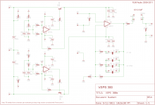
V++/V-- is the "raw" rectified DC, the output from the rectifier diodes.
V+/V- is the "regulated" DC, the output from the filter/regulation circuit
IN+/-, OUT+/- are the audio signals.
plus I'll award the following as Bibio wrote them,
"earth is a path to 'mother earth' in a mains AC circuit (not available in all countries)."
"COM is a 'common' return path for electronics DC."
however,
"ground is actually 'screen' and not connected to anything but it's self in an electronic non mains circuit and used for the audio."
is not quite right, though that's more my fault than Bibio's.
"Ground" is all the non-isolated, metal components in your audio component that are not part of the electric circuit and which are nominally supposed to be at 0 V potential. variously also called: the case, chassis, box, screen, shield etc. A quick Google search tells me I should be calling this "Chassis ground", but I never use "ground" to refer to anything else so in my mind the qualifier isn't needed.
Ground may or may not be connected to earth. Not everyone has 3-wire electrical outlets (I don't). If you do, and your component has AC line voltages running into it (i.e. it contains the power transformer) then you should connect the chassis to earth. The circuit common normally connects to chassis ground at a single point, but this connection can be "lifted" by various techniques to prevent systemic ground loops (arising when the multiple components are connected to earth, and the circuit common, over the whole audio playback chain, ends up connected to this earth at multiple points). The most common is a small resistor and a pair of parallel diodes connected with opposing cathodes. I've also seen a resistor in parallel with an electrolytic capacitor.
Final note, just in case: "lifting" the circuit common from the chassis connection is cool, if you have to do it. "lifting" the earth connection from the chassis is not cool.
Last edited:
lovely neat build. will be interesting to hear your evaluation on the sound as from what i have read elsewhere people seem to love the sound.
Thanks
") First impression is... it needs to run in a bit. Soundstage sounds very promising tough. I will write some more after a couple of hours use.
First impression is... it needs to run in a bit. Soundstage sounds very promising tough. I will write some more after a couple of hours use.I dunno... I think your coupling capacitors are still too small.
They are Obbligato's I had lying around from another project. About the VSPS 300 kit: easy to build for non electronica guys like myself. Manual is clear and easy to read. After checking the voltages I connected a turntable for the first time to my set in more than 20 years. And.... everything worked as advertised! Great! As said in my previous post it needs to run in a bit but is sounds very promising already.
I have one question tough: I could use more gain. Is that possible? If so: how?
Please allow at least 48h powered up for the electrolytics to settle. Breaking in the coupling cap takes a lot longer, and only happens while actually passing a signal, but the changes are comparatively small. For the impatient: Putting an AC voltage into the coupling caps C3 for a couple of weeks before soldering them into the boards will probably do the trick.
VSPS gain is adjustable +/-10 dB, but it requires changing two resistors, R2 and R3. See here.
VSPS gain is adjustable +/-10 dB, but it requires changing two resistors, R2 and R3. See here.
Last edited:
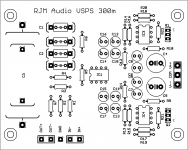
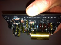
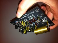
power supply working
it aint pretty but it works.
now just to get the phonoclone and sapphire together.
it aint pretty but it works.
An externally hosted image should be here but it was not working when we last tested it.
now just to get the phonoclone and sapphire together.
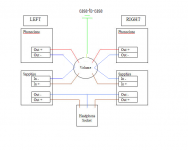
well i'm confused again. looking at the ladder type volume i have i can't work out how to wire that thing up but i sort of have an idea so i will give 2 ways i think it goes.
there are only 3 wires on each side. one is for ground, the other is in and the other is out so does not include the negative side of the signal.
1st way:
2nd way:
or am i barking up the wrong tree?
there are only 3 wires on each side. one is for ground, the other is in and the other is out so does not include the negative side of the signal.
1st way:
An externally hosted image should be here but it was not working when we last tested it.
2nd way:
An externally hosted image should be here but it was not working when we last tested it.
or am i barking up the wrong tree?
Last edited:
Something I said earlier might have led you in the wrong direction.
Neither of those diagrams is correct.
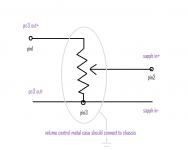
A volume control has three pins per channel, the wiper (output, pin 2), the top (input, pin 1) and bottom (common or "ground (bad)", pin 3) of the resistive element. Pin numbers are for the diagram below, not meant to refer to a specific device.
The common, as the name implies, has to connect to both the input and output returns, IN- and OUT-.
What some people forget is that the metal parts of the volume pot. must have a good connection to the circuit common also, otherwise the volume control will will pick up hum and noise. You don't normally need a dedicated wire, the connection is usually made through the front panel to the chassis, and from the chassis back to COM via the GND connection wire.
Neither of those diagrams is correct.
A volume control has three pins per channel, the wiper (output, pin 2), the top (input, pin 1) and bottom (common or "ground (bad)", pin 3) of the resistive element. Pin numbers are for the diagram below, not meant to refer to a specific device.
The common, as the name implies, has to connect to both the input and output returns, IN- and OUT-.
What some people forget is that the metal parts of the volume pot. must have a good connection to the circuit common also, otherwise the volume control will will pick up hum and noise. You don't normally need a dedicated wire, the connection is usually made through the front panel to the chassis, and from the chassis back to COM via the GND connection wire.
Attachments
Question about R1 & R2; I have a dynavector 20X2 card and from the specs of it i get:
R1= 5 ohms, R2= 166 ohms.
However i don't have these values in decent quality resistors, and also sometimes i use my old 103r for off road flea market records.
So what is wise, use the standard resistors or get some ok quality metal resistors in these values from my local electronics store?
Is there a big sonic difference?
Thanks Gerben
Having the correct resistance value is infinitely more important than having the correct brand/type of resistor. The dynavector is substancially different electrically from the Denon, if the phonoclone is set up correctly for one, it will not have the correct gain for the other.
Last edited:
funny i was thinking of this the other day there. i had a thought of using computer motherboard jumpers with resistors soldered on then cut the jumper bar out so it would be a case of just swapping out the resistor/jumper with the values you need.
would it matter if the board had leads coming from the pins so you could rig up a remote access panel on the case or would the wire cause to much resistance?
would it matter if the board had leads coming from the pins so you could rig up a remote access panel on the case or would the wire cause to much resistance?
I now solved it with dip sockets, my local electronics store had some that really snapped onto resistors.
Shame they don't make these things as single sockets instead of only rows that you have to break.. doesn't look that good but does the trick!
Shame they don't make these things as single sockets instead of only rows that you have to break.. doesn't look that good but does the trick!
Attachments
Last edited:
- Home
- Source & Line
- Analogue Source
- The Phonoclone and VSPS PCB Help Desk