That? Well, that's the complicated bit. It works out to,
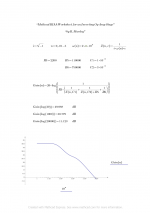
1/[1/R7+1/(Z(C2)+R8)+1/Z(C3)] ,
where Z(C2)=j/(2 pi f C2) and Z(C3) = j/(2 pi f C3).
then you divide that by R4 and take the magnitude of the whole thing to calculate the gain.
Works perfectly too, I just checked using MathCAD. The free version is sufficient to do these calculations:
Gain2(20Hz) = 48.393 dB
Gain2(1kHz) = 27.348 dB
Gain2(20kHz) = 7.551 dB
That's just the second stage, mind you, but working through the rest will add nothing to change the story. As I said, your RIAA network uses the wrong values, and the bass response is too high as a result. The only reason it worked in your other circuit was because R7 needed to compensate for a parallel impedance presented by the amplifier circuit itself.
Can we please (pretty please) put the conspiracy theories to bed now?
Last edited:
Hi all - I made some modifications to my VSPS. Of course I simulated ") D) the result first.
D) the result first.
Here's what I've done:
The end-result is a near-flat response
The resistor and capacitor attenuate the ever-rising response of the VSPS. I figured it couldn't hurt. Somehow on mine after actual measurement (as in -no sim-), crosstalk improved as well. Oh, you do lose 1dB of gain.
D) the result first. Here's what I've done:
An externally hosted image should be here but it was not working when we last tested it.
The end-result is a near-flat response
An externally hosted image should be here but it was not working when we last tested it.
The resistor and capacitor attenuate the ever-rising response of the VSPS. I figured it couldn't hurt. Somehow on mine after actual measurement (as in -no sim-), crosstalk improved as well. Oh, you do lose 1dB of gain.
To "remove" the forth time constant just set R3 to zero ohms (short). There are some arguments in favor of a low pass filter on the output in general, except that your output impedance is now 3.3k, which is little high frankly.
Remember that the response of the VSPS is not "ever rising". In absolute terms it just stops falling. Only when comparing with the RIAA response would it appear to rise.
Remember that the response of the VSPS is not "ever rising". In absolute terms it just stops falling. Only when comparing with the RIAA response would it appear to rise.
Ah, yes, but I followed your remark there: "without R3 the impedance of the feedback loop approaches zero at high frequencies" - causing distortion. So I figured it would have been better to do this with a simple RC-filter after the feedback loop. It's actually just one component more.
Yes, when comparing with the RIAA response it appears to be rising, good correction there. I figured this could be an issue with high-output MC's like the Denon DL110, or an MM like the Nagaoka JT-555,.. The frequency response of those runs way higher than 20kHz.
The change is hardly noticeable at all. Though you can pick up changes if you know where to listen. Certain "hot" records sound a bit less "distorted" when there's high frequency noise. Kind of like less sibilance.
Last edited:
As an insurance measure, an RC filter on the output like you implemented seems like a good idea to me. My only concern is the output impedance is now 3300 ohms.
Ah, yes - that's what I'm still figuring out how to solve that one with minimal components involved. Problem is that it would be a Not So Very Simple Phono Stage
edit: 300Ohm/10nF seems a good match as well. 300Ohm would still meet a decent impedance.
Last edited:
Another addition: 187Ohm (E48) and 15nF (e.g. Wima FKP2 2.5%) would make +- the same sim. And the output impedance is acceptable.
An externally hosted image should be here but it was not working when we last tested it.
Last edited:
Well, yes. It's just a simple RC low pass ... double the capacitance, halve the resistance and you get the same response... while the impedance halves.
You might find it instructive to plot the current through R9 as a function of frequency. At high frequencies it is essentially shorted to ground. The condition you wished to avoid (a very low impedance at high frequency in the feedback loop) is resurfacing in the output load.
You might find it instructive to plot the current through R9 as a function of frequency. At high frequencies it is essentially shorted to ground. The condition you wished to avoid (a very low impedance at high frequency in the feedback loop) is resurfacing in the output load.
First time posting in the thread.
I received my VSPS 300 kit a couple of days ago, and built the PCBs with included parts, very straightforward (great quality PCBs btw)
Next is the PS part, and this is where things get a bit more complex.
I'll be using an 12-0-12V EI core transformer rated at 3 Amps (which equates to 36 VA)
The transformer (a custom wound unit), unlike most toroidal transformers, does not have separate secondaries, it has a common center tap for the secondaries.
I know I can try to fiddle with it and get to the spot where the secondaries are spliced together, So the questions are:
1- Would it matter if the diode bridges share the center tap instead of each bridge having it's separate connection?
2- Would the EI core perform noticeably worse than an equivalent Toroid? (Toroids in Lebanon are hard to come by)
3- Would adding capacitors on the bridge output help the sound in any way by smoothing the power fluctuations?
4- The diode bridges are rated at 6 amps, and are a no name brand, how critical is this part? what are you guys' impressions on better rectifier options?
I've searched the thread for answers, and found some posts relating to the diode part, with people preferring discrete diode bridges while others found prepackaged bridges to fair better. On the other hand, I couldn't find anything about the transformer part and would prefer to delay the build until I get someone knowledgeable to chime in rather than blow up the transformer or even worse, the VSPS...
Regards
Nick
Hello Hajj,
I've experimented with 2 bridges instead of one, but I could not hear any difference. You're more than ok with one..
No idea on the toroidial/EI. In any case, don't put them too close to your preamp. Adding capacitors might smooth things out even more, however, might be pretty useless. Test it out 6 amps is more than enough At 50hz, any diode is good enough
I've experimented with 2 bridges instead of one, but I could not hear any difference. You're more than ok with one..
No idea on the toroidial/EI. In any case, don't put them too close to your preamp. Adding capacitors might smooth things out even more, however, might be pretty useless. Test it out
6 amps is more than enough At 50hz, any diode is good enough Hi Wirehead,
Thanks for the reply!
I guess I should stop obsessing and make do with what's available then
I'll keep the PS and the preamp far from each other (1 meter long XLR umbilical)
But one thing I don't get in your post is the rectifier part.
How could one get +12,0,-12v from one single bridge?
My (limited) understanding says you can either get 12,0 or 24,0 (actually this should be 12xSqrt2 and 24xSqrt2) depending on how you wire the secondaries to the bridge (as said earlier, my transformer has only three wires coming out of the secondaries, 12,0,12)
Thanks
Nick
A couple more questions:
1- If I am to connect two rectifier bridges with them sharing the center tap, would it work? would it cause problems?
2- Where I live we do not have earth connection in the power outlet, only L and N. Will that influence the way I should build the PS?
Thanks
Nick
1- If I am to connect two rectifier bridges with them sharing the center tap, would it work? would it cause problems?
2- Where I live we do not have earth connection in the power outlet, only L and N. Will that influence the way I should build the PS?
Thanks
Nick
Here's a good example:
http://www.elecircuit.com/uploads/allimg/100822/1925495P9-0.gif
J1 and J3 go to transformer line, J2 is connected to the center tap.
Why would you want to use two bridges in this kind of setup?
http://www.elecircuit.com/uploads/allimg/100822/1925495P9-0.gif
J1 and J3 go to transformer line, J2 is connected to the center tap.
Why would you want to use two bridges in this kind of setup?
Why would you want to use two bridges in this kind of setup?
I wanted to stick to the original diagram as much as possible.
The option to use two bridges is only available if you have two secondaries, rather than a single winding with center tap.
You can use an EI transformer, but don't add filter capacitors. The capacitance on the board itself is already sufficient.
The EI transformer output is 12-0-12. "0", the center tap, connects to COM, the top and bottom of the winding connect to the "~" terminals of the bridge, V++ and V-- connect to the "+" and "-" terminals of the bridge.
Attachments
- Home
- Source & Line
- Analogue Source
- The Phonoclone and VSPS PCB Help Desk