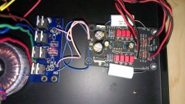
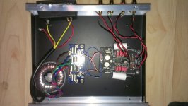
I'll post them, re-sized, for Dimkasta and the rest of you following along.
It ain't a pretty build, but once he fixes the incorrectly oriented LM7912 and connects GND to the chassis it should work, probably ... maybe.
It ain't a pretty build, but once he fixes the incorrectly oriented LM7912 and connects GND to the chassis it should work, probably ... maybe.
Attachments
Last edited:
once he fixes the incorrectly oriented LM7912 and connects GND to the chassis it should work, probably ... maybe.
Yep that sounds right.
Small question, can't figure this one out... So I've got a toroid with a double winding, double rectifier; 7815/7915 (V++ = 15V; V- = -15V) and floating earth (COM).
If I look at the construction guide; you see that COM is not directly connected to Ground (VSPS-case).
Now, in the schematic, this is connected. So you have a floating earth; connected to GND at some point.
If I measure this floating earth; I get a 96V ac-difference to GND - you can even feel it! (I don't get this.. it's behind the rectifiers and regulators, so it shouldn't have that ...)
Pretty lost here to why that AC component is so huge.. could be the source of the 50Hz noise I still have..
I ve been at your place a few months ago. In my case this was just normal operation of the transformer. Since the screw goes through the hole of the toroid, it acts as a secondary and creates some voltage.
If you properly ground the case (as you should), it should go away.
That is if there isn t something else really wrong with your setup.
If you properly ground the case (as you should), it should go away.
That is if there isn t something else really wrong with your setup.
@wirehead.be
I'm not following you completely. Are you using the LM7815/7915 before the VSPS? You shouldn't, since there are LM7812/7912s on the board itself. Just feed the board V++,COM,V-- from the unfiltered rectifier output.
Second point: as shown on the schematic, GND and COM do connect, they share common traces on the board. For simplicity I don't show these internal connections (GND to COM, IN- to COM, OUT- to COM) in the hookup diagram on the construction guide.
V=IR. If you measure the voltage between the power supply COM left floating, and some metal part of the chassis, the resistance is nearly infinite, so any minute current will put the voltage at very high levels. As soon as there is a physical ground connection from COM to the chassis though, even through your fingers, this potential will disappear.
So you should not be able to "feel it", even though a voltmeter will detect it.
You may have a problem. Bad or poor quality transformer, primary or secondary windings hooked up with neutral-hot reversed... without more information or a photo I can't really comment further.
Attachments
@wirehead.be
I'm not following you completely. Are you using the LM7815/7915 before the VSPS? You shouldn't, since there are LM7812/7912s on the board itself. Just feed the board V++,COM,V-- from the unfiltered rectifier output.
Second point: as shown on the schematic, GND and COM do connect, they share common traces on the board. For simplicity I don't show these internal connections (GND to COM, IN- to COM, OUT- to COM) in the hookup diagram on the construction guide.
V=IR. If you measure the voltage between the power supply COM left floating, and some metal part of the chassis, the resistance is nearly infinite, so any minute current will put the voltage at very high levels. As soon as there is a physical ground connection from COM to the chassis though, even through your fingers, this potential will disappear.
So you should not be able to "feel it", even though a voltmeter will detect it.
You may have a problem. Bad or poor quality transformer, primary or secondary windings hooked up with neutral-hot reversed... without more information or a photo I can't really comment further.
Hi rjm,
Well, I've got the power supply (incl. regulators) in one housing, and everything pre-amp related in another (I've not used your PCB). But it seems to be strictly a PSU issue, so I'll go ask this in the PSU-subforum. I can't earth the PSU casing to GND; because I would get a ground loop through my amp (I've got a Digital Cable decoder who is grounded through the coax ; effectively grounding my amp ...). The casing of the preamp is grounded to the virtual ground of the PSU (otherwise I have more noise..). But if I measure this ground, compared to a real ground (say - my amp). I measure about 96VAC. Sure, this is really, really low current - it doesn't trip the ground current switch in my house - but you can feel it. And that's what got me wondering if that is the 50Hz noise I still see when measuring the VSPS noise floor.
The psu is made up of a double toroid; 2 rectifiers; 2x 2200uF caps; 7815 & 7915 with protection diodes over them; 100nF decouple caps,.. Might just be a limitation of the PSU..
I can't earth the PSU casing to GND; because I would get a ground loop through my amp (I've got a Digital Cable decoder who is grounded through the coax ; effectively grounding my amp ...)
The earthed cable connection can be a pain in the *** with in comes to system grounding.
However with separate cases for the power supply and preamp, you can get around the problem without lifting the PSU earth, which is, as Dimkasta points out, poor practice. (Though many commercial components only have two wire power cords, or did until recently.)
The power supply chassis is connected to the power line earth. The power supply COM, however, does not connect to the power supply chassis.
The power supply COM runs over to the VSPS box, to the board, and the circuit common, which is connected to the VSPS chassis though, on my boards, the GND pad, but can be from whatever point you choose. The VSPS chassis and the power supply chassis are NOT connected.
That normally works.
/R
Ah yeah sorry about that. I had a separate psu case in mind.
An alternative might be to use something like Pass`s rectifier-thermistor trick to earth the case to the socket`s earth. I have seen others using a cap to do this.
This will require a non-metal IEC socket though, so that you can feed the case`s earth through the separating components, and then to the earth terminal of the IEC.
Dim,.....................An alternative might be to use something like Pass`s rectifier-thermistor trick to earth the case to the socket`s earth. I have seen others using a cap to do this.
This will require a non-metal IEC socket though, so that you can feed the case`s earth through the separating components, and then to the earth terminal of the IEC.
I think you have got this wrong.
The metal Chassis must be connected direct to the third wire (PE) in the mains cable. No other components or wires in between. NONE !!!!
Connect the external conductive parts to the chassis. It is here that you can use a Disconnecting Network (DN). But, very importantly, that DN must be able to pass Mains Fault Current from Main Audio Ground to PE.
Allright, I finally cracked it. So my vsps is in two separate housings. One is toroid+bridges+caps & regs; the other is purely the vsps. So the cable between the two housings is running DC. It was filtered adequately (and the opamps decoupled with 100nf to gnd; parallel with 1uf tantal). So I had a ferrite core lying around, figured I'd take a look what would happen with that. Snapped it on as close to the preamp as possible, on the cable running DC power: 50hz hum gone. So was the occasional faint radio hum when my amp was at full volume. So this brings me to the following: was this purely due to the fact that I have a long DC-cable feeding the vsps instead of AC and regs on the vsps board?
@wirehead
I do get the occasional reports of RFI pickup. Usually the Phonoclone, though. I don't recall anyone having a problem with the VSPS, but your configuration is non-standard in that you have the regulators in the power supply rather than in the VSPS chassis.
If the ferrite works, I'd be inclined to give thanks and call it a day.
Various other options include moving the regs to the main chassis, or using shielded power cable. The thickness (gauge) or the cable won't have any significant effect on anything here.
@wirehead
If the ferrite works, I'd be inclined to give thanks and call it a day.
Various other options include moving the regs to the main chassis, or using shielded power cable. The thickness (gauge) or the cable won't have any significant effect on anything here.
Indeed, very happy now that the last bit of noise is gone now. I took another critical view at the wiring to get it even lower and twisted every conductor of 220V inside the PSU casing. Also made sure the umbilical cable feeding the VSPS (the twisted pair..) actually carries V- and V+ over a twisted pair, to make sure nothing gets picked up.
@RJM
Took the time to do some measurements, shows what the VSPS is possible of:
-First; the 1kHz reference signal. When I maxed out the signal, to the input of my Edirol FA-101 interface; there's still an offset of -9dB (the ripple of the signal was a "clicking" noise when taking a screenshot..):
-Now, if we take note of this -9dB offset, this is what the VSPS is possible of:
Pretty silent now Still well in -90dB range taking note of the offset. So as said, measured with the reference signal @ 1kHz and with 1K resistors on the input.
Very happy
Took the time to do some measurements, shows what the VSPS is possible of:
-First; the 1kHz reference signal. When I maxed out the signal, to the input of my Edirol FA-101 interface; there's still an offset of -9dB (the ripple of the signal was a "clicking" noise when taking a screenshot..):
An externally hosted image should be here but it was not working when we last tested it.
-Now, if we take note of this -9dB offset, this is what the VSPS is possible of:
An externally hosted image should be here but it was not working when we last tested it.
Pretty silent now
Still well in -90dB range taking note of the offset. So as said, measured with the reference signal @ 1kHz and with 1K resistors on the input.Very happy
RJM,
i have a Denon 110 HOMC cartridge. Output is speced at 1.6mv, 160 ohm impedence. I have successfully used MC phono stages in the past, loading them at 8K. I need the extra gain as I am running a passive preamp (attenuator in font of a tripath amp).
Is your recommendation to avoid the phonoclone and go for the VSPS for HOMC cartridges due to the gain factor of the phonoclone (overloading) or the zero impedence nature of the phonoclone? I could use the phonoclones extra gain, not sure if the zero impedence design will play well with the relatively high impedence of a Denon 110.
Also, any experience/thoughts on using switch mode (brick-type) power supplies with either the phonoclone or VSPS?
- Home
- Source & Line
- Analogue Source
- The Phonoclone and VSPS PCB Help Desk