Just bundle 2-3 of what you use now in parallel.
Nope. You've moved the input return to share a common length of wire with the output return, when it did not before.
If there is a ground loop there, it is present anyway.
Nope. You've moved the input return to share a common length of wire with the output return, when it did not before.
OK the gain resistor was a nice opportunity to correct some "issues" on my build.
First of all, the gain now is down to 58db nominal with R2 being 300ohms.
Second the voltages at the opamps are at their proper levels (~9,7) by switching R11-R14 at the X-reg to 27k. To anyone reading, this is specific to my transformers (Hammond 182 series). Do not do this change in yours unless you know what it means.
Third, the grounding scheme has changed to the proper one.
Impressions overeall:
Richard you were right. The phono is so silent know that I had to crank it up to quarter past to get a hint of hiss out of the speakers. And absolutely no RF or humm.
The sound seems to have more punch at the same sound levels (not volume pot position) despite the really lower gain. It seems that 8,8V is too low for the circuit after all. Anyone using Hammond 182 series beware.
Now to break it in again.... Damn I hate this phase... Not that I do not like what I hear now, but I am really curious what will it become in a month or so
Last edited:
Received and soldered up the VSPS today, waiting for some caps and psu parts
Now just have to decide to buffer this or the volumecontrol...
Looks very cool, and some big Ampohm caps would definately warrant seetrough boxes
Hello, just ordered phonoclone3 kit and now in process of ordering rest of parts. I use Denon DL-103 cartridge on Rega P5 turntable. As I understand, in gain calculator by default are listed optimum values of resistors R1 40ohms and R2 1.333kohms for above mentioned cartridge. However in BOM R1 is listed as 47,5 ohms and R2 1kohm.
Should I order resistors according to gain calculator or stick with BOM? Cartridge impedance is 40 ohms and output 0,3mV.
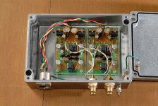
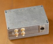
Another question is enclosure - I plan to use one chassis for pcb's and psu, isolating pcb's from dual triad 50va transformers by metal shield. Is it ok or it will affect performace a lot?
Should I order resistors according to gain calculator or stick with BOM? Cartridge impedance is 40 ohms and output 0,3mV.
Another question is enclosure - I plan to use one chassis for pcb's and psu, isolating pcb's from dual triad 50va transformers by metal shield. Is it ok or it will affect performace a lot?
Phonoclone RC
If anyone is interested in a pre-built phonoclone on the cheap, please see this
Google+ post.
It's a older version I built a while back. The "RC Limited" boards were half the size of the current Phonoclone 3, and used LM7xxx regulators with a small RC filter on the output to filter the regulator output noise.
My version has Riken Ohm carbon resistors in critical positions, some fancy low impedance electrolytics I was given to try, mica caps, and 4x socketed OP27 from Analog Devices. It's configured for the DL-103, i.e. stock gain.
You need to use your own power supply (12x2 VAC, diodes), and connect it to the 3 pin SLR on the phonoclone case.
Attachments
Last edited:
Finished both boards and finally received psu parts. Now I am ready to breadboard everything and have question regarding grounding.
Rega is grounded through one of rca sockets (as I remember - left channel). Is it enough to connect vin- and vout- from respective boards to respective rca sockets and separately ground from boards to power socket ground? Maybe best solution would be to connect ground from both boards and all sockets at one point as dimkasta did (posts 2036 and 2039) and leave vout- and vin- not connected as it looks like in photo?
I am pretty sure, that I will have hum through ungrounded turntable rca socket, as I had it when wired step-up transformers. Hum was gone only when grounds from both inputs and outputs were connected together (respectively). Hope that everything will go fine and I will not have to bother you with further check-out questions
Well, it works , no hum at all hope it will be that way when I will put it in case. Any ideas how much time break in will take? Sounds much better than project phono box (that actually sounds like rubbish) even without break in. Waiting for a friend that owns similar rega setup with LP's that he likes and listens to a lot, so it's going to be serious listening session with a bottle of wine tonight
hope it will be that way when I will put it in case. Any ideas how much time break in will take? Sounds much better than project phono box (that actually sounds like rubbish) even without break in. Waiting for a friend that owns similar rega setup with LP's that he likes and listens to a lot, so it's going to be serious listening session with a bottle of wine tonight Peter' s instructions are clear enough
http://www.diyaudio.com/forums/audio-sector/149672-universal-power-supply-pcb.html
http://www.diyaudio.com/forums/audio-sector/149672-universal-power-supply-pcb.html
You can solder a standoff into the pad, and solder the two wires to the standoff (standoff: a short length of resistor lead, etc.). Or you can do what I sometimes do: solder in one lead with a little space left between the insulator and the board, wrap the lead of the second wire around the first in the open space, and solder.
- Home
- Source & Line
- Analogue Source
- The Phonoclone and VSPS PCB Help Desk