But if there is some noise on the input from those resistors, isn t that being amplified with the rest of the signal?The output noise of the phonoclone is defined by the op amp, not the input resistors, so there is technically no advantage in using low noise resistors.
Thanks!
Thanks,
I did fix all issues.
In the VSPS 300 Dual-Mono MM Phono Stage with X-reg setup it's furnished, for capacitors C3, two white coaxial AV 1.7uF (1.9uF measured). Did someone try other capacitor brands please? Any comments about C3, please?
Warm regards,
Ion
Thanks,
I did fix all issues.
In the VSPS 300 Dual-Mono MM Phono Stage with X-reg setup it's furnished, for capacitors C3, two white coaxial AV 1.7uF (1.9uF measured). Did someone try other capacitor brands please? Any comments about C3, please?
Warm regards,
Ion
Caps are like ice cream... depends on what you like and how much money you got to spend 
If your pockets are deep enough, they can even have gold in them (both ice cream and caps)
Now before you go around changing stuff, make sure that you give your phono a chance to properly break-in. That includes both C3 and the regulator caps, inner and outer wiring and the entire construction in general. From my experience, a month of moderate daily listening is more or less enough. And changing as much as a bridge wire or resoldering a component can bring the process back for the system.
After that, you can start switching stuff, giving them in turn enough time to break-in before you make any judgement on their performance.
Now if you need a more specific answer on cap brands, you will have to balance yourself price and performance expectations. Personally I also took into account my personal no-specific-reason liking towards brands and looks (yeah I admit it... I m shallow). I tried the vishays that Richard sent me with the kit for a month or so, then switched to Mundorf Supremes (no oil, no gold, plain black ones). A friend also built a p2p phono very close to VSPS and tried Solen and Auricaps, but he is using a custom made transformer stepup that I really do not like, and he keeps switching them before (imho) they have the chance to break-in and get comfortable.
From my up till now experience, I still vote for Mundorf. I would like to test some VCaps at some point, but for now my pockets a bit shallow...
If your pockets are deep enough, they can even have gold in them (both ice cream and caps
)Now before you go around changing stuff, make sure that you give your phono a chance to properly break-in. That includes both C3 and the regulator caps, inner and outer wiring and the entire construction in general. From my experience, a month of moderate daily listening is more or less enough. And changing as much as a bridge wire or resoldering a component can bring the process back for the system.
After that, you can start switching stuff, giving them in turn enough time to break-in before you make any judgement on their performance.
Now if you need a more specific answer on cap brands, you will have to balance yourself price and performance expectations. Personally I also took into account my personal no-specific-reason liking towards brands and looks (yeah I admit it... I m shallow). I tried the vishays that Richard sent me with the kit for a month or so, then switched to Mundorf Supremes (no oil, no gold, plain black ones). A friend also built a p2p phono very close to VSPS and tried Solen and Auricaps, but he is using a custom made transformer stepup that I really do not like, and he keeps switching them before (imho) they have the chance to break-in and get comfortable.
From my up till now experience, I still vote for Mundorf. I would like to test some VCaps at some point, but for now my pockets a bit shallow...
Hello,
I appreciate your answers. Thank you for your ideas.
In my opinion $15 x 2 it's less important. Your experience is very important for me.
I would wish make the sound of my VSPS as good as, reasonable, possible.
More details about what Mundorf, in your experience, would be more appropriate for VSPS 300i, please?
Or what Multicap capacitor, please?
Have a nice day!
Warm regards,
Ion
Richard I just received the phonoclone kits. Once again thanks a lot for nice communication and a wonderful kit.
Quick question.
I have also received some Salas BiB boards and I would love to test them on the Phonoclone.
If I choose to populate the x-reg part as well and then decide to use the V+ and V- terminals to input power from the BiBs, do I need to remove/omit anything from the X-reg parts?
Quick question.
I have also received some Salas BiB boards and I would love to test them on the Phonoclone.
If I choose to populate the x-reg part as well and then decide to use the V+ and V- terminals to input power from the BiBs, do I need to remove/omit anything from the X-reg parts?
And something else.
I noticed that GND, IN- and OUT- are electrically connected. I guess this means that we can use non-isolated RCA sockets and just run one wire from GND to the chasis ground post? Leaving IN- and OUT- holes unconnected?
Am I forgetting something? Because if not, this ends up a very nice and clean internal wiring scheme.
Unfortunately it s getting late and I cannot drill the new chassis now...
I ll have to wait until tomorrow to test stuff
Star Earthing connects all earth potentials at the same point. Helps prevent earth loops, and sounds better as well
1. The phonoclone board was not designed to be powered via V+ and V- when the X-reg circuit is populated. At the very least, you should not have Q1,2 and IC3,4 on the board. The rest the components won't be a problem.
2. Yes, COM, GND, IN- and OUT- are connected internally, in the correct order. If you don't connect the input RCA signal return to IN-, but connect it to the case via a non-isolated jack, you are re-routing it through some potentially noisy pathways. I doubt what you propose will work well, if at all.
P.S. Star earthing is for dummies.
2. Yes, COM, GND, IN- and OUT- are connected internally, in the correct order. If you don't connect the input RCA signal return to IN-, but connect it to the case via a non-isolated jack, you are re-routing it through some potentially noisy pathways. I doubt what you propose will work well, if at all.
Makes sense.
How about running a single wire from GND to the ground post and then IN- and OUT- again to the ground post. So basically moving the single point from the board to the the GND post. But with significantly less wiring flying around the box collecting and emitting noise.
Nevermind it worked wonderfully
Even with the volume to max, I get no hum at all.
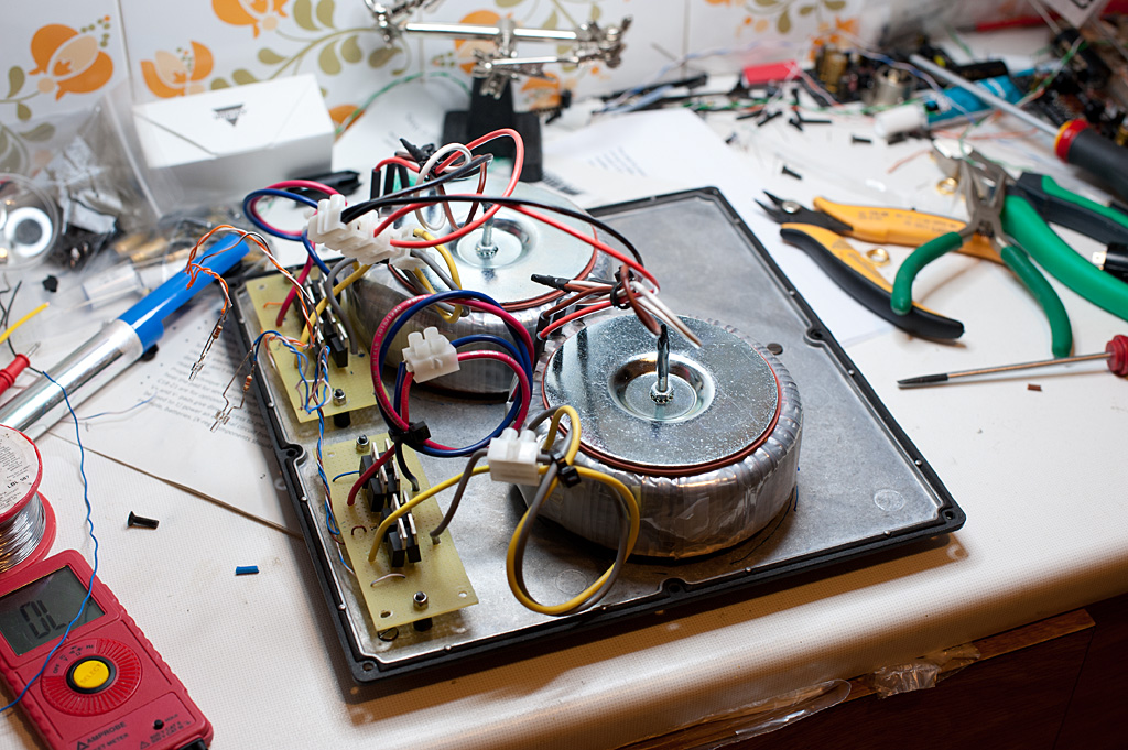
Here is some porn from the new setup.
I finally switched to a 6pin XLR to keep the cables on the back tidy. The cable was custom made by removing the solid core wires from a 3wire power cable I had around, and wrapping it in polyflex tube. Nice, tidy and beautiful. I forgot to take a photo and now I m listening to my new toy, so I ll post one later.
Setup on the PSU remained the same. I changed only the XLR socket. Here it is before soldering the wiring to the socket and closing it.
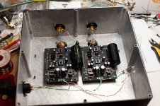
And here is the phonoclone boards on their new home.

The ground cables are soldered on the bottom side of the boards to keep the wiring as clean as possible. If you remember my previous photos, you will notice that the input is still on the top of the case to allow for shorter tonearm cable and keep it away from the power and output ones.
And as stated above, the RCA sockets are insulated, but the - ends go to the ground post instead of to the boards, and meet there with the GND from the boards. Nice and tidy.
Mundorf Supremes were used again for C3.
And if you look closer you will notice that I chose to not use the Nichicons caps. I decided to give the Panasonic FRs a chance.
So far I like what I hear a lot. It s late so I cannot do any proper listening, but I get the feeling that the Panasonics will not require so much breaking in as the Nichicons.
Once again, consider me a happy DIYer
And a small suggestion for the next revision of the boards. It would be nice to reserve some small space to include a current limiting resistor and pads for indicator leds on the X-reg. I used the V+ and V- this time, but it would be nice to have them nice and tidy on-board, and just run a twisted pair from the board to the led.
Oh and another one. It would be nice to have a jumper or something to allow isolation of the X-reg from the rest of the board. Both for voltage or full psu tests.
Once again thanks for a wonderful phono Richard
Even with the volume to max, I get no hum at all.
Here is some porn from the new setup.
I finally switched to a 6pin XLR to keep the cables on the back tidy. The cable was custom made by removing the solid core wires from a 3wire power cable I had around, and wrapping it in polyflex tube. Nice, tidy and beautiful. I forgot to take a photo and now I m listening to my new toy, so I ll post one later.
Setup on the PSU remained the same. I changed only the XLR socket. Here it is before soldering the wiring to the socket and closing it.
And here is the phonoclone boards on their new home.
The ground cables are soldered on the bottom side of the boards to keep the wiring as clean as possible. If you remember my previous photos, you will notice that the input is still on the top of the case to allow for shorter tonearm cable and keep it away from the power and output ones.
And as stated above, the RCA sockets are insulated, but the - ends go to the ground post instead of to the boards, and meet there with the GND from the boards. Nice and tidy.
Mundorf Supremes were used again for C3.
And if you look closer you will notice that I chose to not use the Nichicons caps. I decided to give the Panasonic FRs a chance.
So far I like what I hear a lot. It s late so I cannot do any proper listening, but I get the feeling that the Panasonics will not require so much breaking in as the Nichicons.
Once again, consider me a happy DIYer
And a small suggestion for the next revision of the boards. It would be nice to reserve some small space to include a current limiting resistor and pads for indicator leds on the X-reg. I used the V+ and V- this time, but it would be nice to have them nice and tidy on-board, and just run a twisted pair from the board to the led.
Oh and another one. It would be nice to have a jumper or something to allow isolation of the X-reg from the rest of the board. Both for voltage or full psu tests.
Once again thanks for a wonderful phono Richard
Attachments
Last edited:
P.S. Star earthing is for dummies.
... which is why high end manufacturers like NAIM use star earth (and even star power) in their products.
Last edited:
Richard according to your experience would you consider 68db too much for a 0.4mV cartridge?
I have used 1k for R2 and 12R for R1. My cartridge is a Shelter 501 with 12R impedance and 0.4mV output, giving ~68,4db gain according to the excel worksheet.
My feeling from my initial listening tests, is that it is a bit much.
Your excel proposes an optimum of 58db (agrees with the KAB gain calculator) but to get that R2 has to go to 300R which is below the 500R threashold that you suggest on your website.
What would you suggest? Should I go for 500R and ~63db?
Thanks again
@dimkasta
Suggest dropping R2 down to 300R. My original comment about loading didn't take into account the very small signal swings involved, there appears to be no disadvantage to lower values.
Thanks for the photos, your latest build looks really nice. I'm a surprised your connection scheme worked, as formally connecting IN- and OUT- at the ground lug means the a short but textbook "ground loop" is created : the output currents are impressed onto the input signal over the length of wire going back to the board.
The phonoclone boards have the IN-, OUT-, GND pads clustered so close together they can be considered interchangeable, but IN- and OUT- should best be kept separate whichever pad you use. That said I doubt you'd be able to hear any difference.
@Mr Onion. Star power? That's impressive! They managed to crack the fusion problem, then...
Suggest dropping R2 down to 300R. My original comment about loading didn't take into account the very small signal swings involved, there appears to be no disadvantage to lower values.
Damn I hate not having R values available...
I'm a surprised your connection scheme worked, as formally connecting IN- and OUT- at the ground lug means the a short but textbook "ground loop" is created : the output currents are impressed onto the input signal over the length of wire going back to the board.
Well my wiring is not elecrically different from you suggested connections. I just moved the IN-/OUT-/GND meeting point from the one side of the GND wire to the other. If there is a ground loop there, it is present anyway.
- Home
- Source & Line
- Analogue Source
- The Phonoclone and VSPS PCB Help Desk