OK I will check your suggestion now.
in the meantime, same test with a different 182P12 and GBPC102-E4/51 rectifiers this time.
EXACTLY the same results.
Further measurements show that the AC on the secondaries (bridge input) is 12,4V at all times.
What changes is the DC voltage on the output of the bridges.
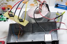
I am also posting a photo of the circuit, in case you have any idea of something that could 've slip my mind. The transformer is wired for 230V operation. White and brown wires are soldered together to give primaries in series. The lower voltage on the output occurs when I feed the phase of the power line to the black(dotted) wire, and the normal when I feed it to the orange. Secondary dotted wires are red and grey.
I also tried with the fuse connected before the black wire. Same behaviour (11.5V when phase is on black).
The case is earthed through the IEC's metal body.
The board of the bridges is a goodish quality protoboard.
On the output side, blue is V-- (xlr pin 2), orange is V++ (xlr pin 1), brown and white are common center (xlr pin 3). No xlr pins are grounded (neutrik chassis socket).

PS the case is too small for the transformer. I just use it for now to keep everything in place. I do not close it for the tests.
in the meantime, same test with a different 182P12 and GBPC102-E4/51 rectifiers this time.
EXACTLY the same results.
Further measurements show that the AC on the secondaries (bridge input) is 12,4V at all times.
What changes is the DC voltage on the output of the bridges.
I am also posting a photo of the circuit, in case you have any idea of something that could 've slip my mind. The transformer is wired for 230V operation. White and brown wires are soldered together to give primaries in series. The lower voltage on the output occurs when I feed the phase of the power line to the black(dotted) wire, and the normal when I feed it to the orange. Secondary dotted wires are red and grey.
I also tried with the fuse connected before the black wire. Same behaviour (11.5V when phase is on black).
The case is earthed through the IEC's metal body.
The board of the bridges is a goodish quality protoboard.
On the output side, blue is V-- (xlr pin 2), orange is V++ (xlr pin 1), brown and white are common center (xlr pin 3). No xlr pins are grounded (neutrik chassis socket).
PS the case is too small for the transformer. I just use it for now to keep everything in place. I do not close it for the tests.
Attachments
Last edited:
I measured the transformer.
Primaries in series are 12.2ohm.
Secondaries are 0.5 ohm each.
When I measure resistance between primary and secondaries I get absolutely no action. Like no connection is detected. Same between the two secondaries on all combinations of wires. Measured with 3 different DMMs.
I guess there is no problem with the transformers after all?
All diodes measure ~0,45V on the diode test of the DMM.
With the phase on the Orange cable, I got:
Between + and blue: 6,3V AC
Between + and red: 5,3V AC
Between - and red: 5,3V AC
Between - and blue: 6,3V AC
With the phase on the Black
Between + and blue: 5,6V AC
Between + and red: 6,4V AC
Between - and red: 6,4V AC
Between - and blue: 5,6V AC
With the phase on the Orange cable, I got:
Between + and blue: 6,3V AC
Between + and red: 5,3V AC
Between - and red: 5,3V AC
Between - and blue: 6,3V AC
With the phase on the Black
Between + and blue: 5,6V AC
Between + and red: 6,4V AC
Between - and red: 6,4V AC
Between - and blue: 5,6V AC
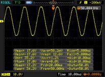
OK... here is the output of the secondaries (while attached to the bridges). It s actually not symetrical... A problem in the power network?

Perhaps it would be a better idea to use a higher voltage transformer and use 7812 and 7912 to get the proper voltages for V++ and V--?
Perhaps it would be a better idea to use a higher voltage transformer and use 7812 and 7912 to get the proper voltages for V++ and V--?
Attachments

Last edited:
I'm beginning to think it's all some measurement artifact. There does not seem to be anything wrong with your power supply.
I'd go ahead and attach to the VSPS and check the measurements again. It might that without filter caps and unloaded, the interaction with your meter/scope is causing strange effects.
Looking at your latest scope trace, and almost certain of it.
I'd go ahead and attach to the VSPS and check the measurements again. It might that without filter caps and unloaded, the interaction with your meter/scope is causing strange effects.
Looking at your latest scope trace, and almost certain of it.
Giving power to either wire (black or orange) with VSPS attached, 15.7V on V++ and -15.7 on V-- (31.4 between them) and -8.8V between ground and pin 4 and 8.8V between ground and pin 7 of IC1.
It s a good thing the x-reg works evening things out")
I probably messed up the capacitors' pads?
It s a good thing the x-reg works evening things out
I probably messed up the capacitors' pads?
Last edited:
Well yes and no.
The math for the caps makes sense (11,3 x 1,4 = 15,6) so there is no problem with the capacitors.
The problem still exists because we need 17,5V on the V+ and 10V on IC1.
Here is the output of the secondaries with VSPS connected.

The two boads draw ~22mA without IC1 and ~32mA with IC1 installed (measured after the bridges).
Could it be that the 182p12 is designed to stabilize to a steady ~12V from the first few mAs instead of the expected 13,4 at low currents?
The math for the caps makes sense (11,3 x 1,4 = 15,6) so there is no problem with the capacitors.
The problem still exists because we need 17,5V on the V+ and 10V on IC1.
Here is the output of the secondaries with VSPS connected.
The two boads draw ~22mA without IC1 and ~32mA with IC1 installed (measured after the bridges).
Could it be that the 182p12 is designed to stabilize to a steady ~12V from the first few mAs instead of the expected 13,4 at low currents?
Attachments
Last edited:
The problem still exists because we need 17,5V on the V+ and 10V on IC1.
Err, well, no.
I was aiming for about +/-10 V on the X-reg outputs, but with the current BOM is usually ends up a little lower. It also varies with the size and model of the transformer, whether you use two bridge rectifiers or one, and what kind of diodes you use.
The X-reg has no absolute reference, the outputs are just a percentage of the input voltages so they do vary a bit from one build to another.
Relax, everything is working fine.
Could it be that the 182p12 is designed to stabilize to a steady ~12V from the first few mAs instead of the expected 13,4 at low currents?
That's essentially it, yes. I'm not sure where you are quoting the 13.4 V(AC?) from, but that's about what you'd expect from that size of toroid when there is no load. Run 20-30 mA off the secondaries, rectified so the conduction angle makes the effective current much higher (about 0.5 A) and the output will settle down to close to the rated 12 VAC.
Last edited:
Yes I ve been studying the x-reg to understand how it works with the voltage divider providing the Vref while pushing noise below the threshold of the op-amp.
It s a bit weird to leave the supply voltage prone to possible fluctuation.
I had an idea that I need to work a bit. it might save us a ton of trouble.
Do you have any idea/estimation what is the noise threshold of the opa27 in the configuration of VSPS/Phonoclone?
About the 13.4V it was more an empirical number from not heavily loaded supplies. But it was also the required value for your circuit's math to add up
I thought the number seemed vaguely familiar.
Yeah, my little calculator is based on the 35 VA transformer specified in the BOM, which peaks to a higher unloaded output than the larger one you are using. It's anyway just a rough estimate. A guide.
Noise of the OPA27? Sure, data sheet says 4.5 nV/sqrtHz at 1 kHz. -167dB, your gain is 40 dB, midband, so roughly -127 dB, rising to perhaps about -100 dB in the low frequencies where the gain is higher and 1/f noise starts to contribute.
It doesn't matter, since for the VSPS the resistor noise of the cartridge is the higher or similar contribution. For the phonoclone, the resistor noise is much smaller (MC), and the device noise of IC1 dominates. Oh, and compared to the surface noise of the record? No contest! Record always wins.
I was thinking about the x-reg part and the noise rejection of the opamp (probably makes my mention of vsps/phonoclone misleading)
I was wondering what is the max V of noise that can be rejected by the opamp input in the x-reg configuration (as per your saying that the divider makes ripple noise so low that it is rejected by the opamp input)
I was wondering what is the max V of noise that can be rejected by the opamp input in the x-reg configuration (as per your saying that the divider makes ripple noise so low that it is rejected by the opamp input)
If I remember, that was referring to how low the ripple / noise had to be made on the voltage divider RC stack. I was pointing out that there is no advantage in making the ripple lower than what was injected anyway through the X-reg op amp power supply inputs.
Let's say the input referred PSRR is 80 dB at the frequency of interest, and that the voltage ripple on the op amp power pins is 100 mV. This is 10 uV of input referred signal. So if the reference input noise is, say already 1 uV, it doesn't make any difference to lower it further as the output noise is dominated by the larger term of 10 uV.
I was just rationalizing how big the filter caps on the voltage divider had to be.
Electrolytics breaking in is harder to pin down. It goes something like this: for the first few hours things are crazy sounding, really loose and sloppy, but also really intense. Then suddenly things go dead and gummed up, and then, over a period of days, of if you really listen closely, weeks or longer, they start to open out, becoming basically clear and transparent.
QFT...
Almost a week or so with the new nichicons (~30 hours of listening) and the phono sounds really low-fi... I hope it breaks in soon... this is really annoying...
The final psu case is on its way along with more MUR860s to replace the Vishays. Also a new 182Q12 transformer (160VA) for more testing. I might try the P as well (225VA) but it's amost reaching the threshold that it will require a soft start... we ll see...
Sigh... I hate having to wait...
I think I've built 3 phonoclones - and all of them have hummmmmmmed a bit. I've always got around it by lowering the gain and also being careful routing the cables. I have done practically every grounding scheme imaginable!!
Anyway, following a bit of a system rearrange for other reasons, I realised I had an almost complete 47 labs clone system - shigaclone, DAC, LM3875 and horns. So I thought, lets put the phonoclone back in and see how it all goes together!
And back came the hum with a vengeance. So I started to look again at it all. I have found out what was causing it - and its the SPDIF feed from the shigaclone.
The shigaclone is always on, and the spdif feed is always on too. I found that if I disconnected the SPDIF feed at the back of the shiga, the hum is gone. If I leave the cable plugged in at the back of the shiga, and disconnect it from the DAC, I still get the hum. Weird? If I use a different dac (buffalo) I still get this hum in the same way.
At least I now know whats causing it - although fixing it might be a bigger struggle.
Fran
No different cases - although all of them were dual mono. I did temporarily change one of them back to regular at one point but it made no difference.
Now, I think this must be RF pickup inducing the hum because as I move the SPDIF cable around I can make the hum almost dissappear.
Poor Richard!! How many different wierdo issues like this crop up!!
Fran
Now, I think this must be RF pickup inducing the hum because as I move the SPDIF cable around I can make the hum almost dissappear.
Poor Richard!! How many different wierdo issues like this crop up!!
Fran
- Home
- Source & Line
- Analogue Source
- The Phonoclone and VSPS PCB Help Desk