Thanks Kor952 and RJM. I will try to find the right info for the cartridge for R1 and R2.
I ripped out all the wires, reversed the transistors and took out the RCA jacks. I connected the power supply and the boards power up, but I haven't had a chance to test them further (damn that weekend yard work).
I have to order some insulated RCA jacks and maybe some better hookup wire. (Has anyone ordered from Percy Audio, Michael Percy Audio Ordering Information)
Inspired by Orion's nice build, I may look around for a better case than my Hammond extruded aluminum box while I am at it. Perhaps I should get one big enough for the B-Board buffer stage too.
By the way, desoldering was a pain for me. I had a lot of trouble getting the transistors off, since they have three pins and it was difficult to get all three pads hot at once. I also had trouble getting the solder out of the holes on the small pads. I have a nice Weller iron and copper solder wick, but it seemed like I was going to burn up the board getting the solder off. Any tricks that I am missing?
John
dimkasta
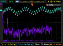
Short the inputs and remeasure the output noise. That's your baseline reference.
The second image shows the output with the cart plugged in? That's 1V rms! What the heck...
60 mV channel difference on 1.5V is an imbalance of 0.3 dB (4%). That's about typical for a cartridge output, but a little high if this is just the VSPS circuit. Right now I'm not sure where your signal is coming from.
john
That's about right for the resistors, it doesn't have to be exact. Desoldering is a total pain, and burning components is a real risk. Especially anything with more than two leads. If I have to do a lot I'd sooner trash the board and start over. No nice way to sugar coat this: learn to do the job right the first time so you never have to desolder anything.
Last edited:
Thanks Kor952 and RJM. I will try to find the right info for the cartridge for R1 and R2.
I ripped out all the wires, reversed the transistors and took out the RCA jacks. I connected the power supply and the boards power up, but I haven't had a chance to test them further (damn that weekend yard work).
I have to order some insulated RCA jacks and maybe some better hookup wire. (Has anyone ordered from Percy Audio, Michael Percy Audio Ordering Information)
Inspired by Orion's nice build, I may look around for a better case than my Hammond extruded aluminum box while I am at it. Perhaps I should get one big enough for the B-Board buffer stage too.
By the way, desoldering was a pain for me. I had a lot of trouble getting the transistors off, since they have three pins and it was difficult to get all three pads hot at once. I also had trouble getting the solder out of the holes on the small pads. I have a nice Weller iron and copper solder wick, but it seemed like I was going to burn up the board getting the solder off. Any tricks that I am missing?
John
For removing items like transistors, cut the legs off from the component first so you can then desolder one at a time. I tend to use solder wick and then a solder sucker. I have bought parts from Michael Percy in the past with no problem.
Regards
OK I will later today when I get home.
By the way, I might be able to borrow a high precision DMM next week.
Is it worth precisely matching each and every component for both channels and power rails?
Or just the RIAA parts?
PS. New mouser package just arrived... oh my... it s gonna be a fun evening")
By the way, I might be able to borrow a high precision DMM next week.
Is it worth precisely matching each and every component for both channels and power rails?
Or just the RIAA parts?
PS. New mouser package just arrived... oh my... it s gonna be a fun evening
New update.
625-GBPC602-E4 Vishay Bridge Rectifiers cause almost twice the ripple (50Hz) in comparison to 4x MUR860G.
The Hammond 182P12 really hates smallish fuses. 250mA fuses were blown to electro-heaven without a chance. 1A fuses last ~5-6 power cycles.
I will try bigger ones today, but it really defeats the purpose of the fuse (causing it to protect merely from hard shortcircuits)
A soft start might be a good idea and should not increase the cost significantly.
Or perhaps using a big 5A on the primary side for general protection against shortcircuit, and a 250mA on each of the secondaries for protecting the phono.
If one of the small ones blows, it will cause single rail reg power, but should not be a prob since X-reg cross exchanges voltages from both rails as references, so if one goes down, then both should go down.
Any thoughts?
By the way, the sonic improvement with the big torroid was amazingly huge.
Last edited:
Are you using slow-blow "T"-typoe fuses? Normally 1A slow blow is sufficient.
I keep saying this, but people don't believe me. I guess it's one of these things that everyone has to try for themselves.
By the way, the sonic improvement with the big torroid was amazingly huge.
I keep saying this, but people don't believe me. I guess it's one of these things that everyone has to try for themselves.
I keep saying this, but people don't believe me. I guess it's one of these things that everyone has to try for themselves.
How big is big? 47 Labs uses one or two 170VA supply's but that's with 2 x 24V, 170 / 48 = 3.5A, 3.5 x 2x12 = 84 VA. Would 84 VA do? or is 2 x 50 VA (2 x mono) OK?
Ronald.
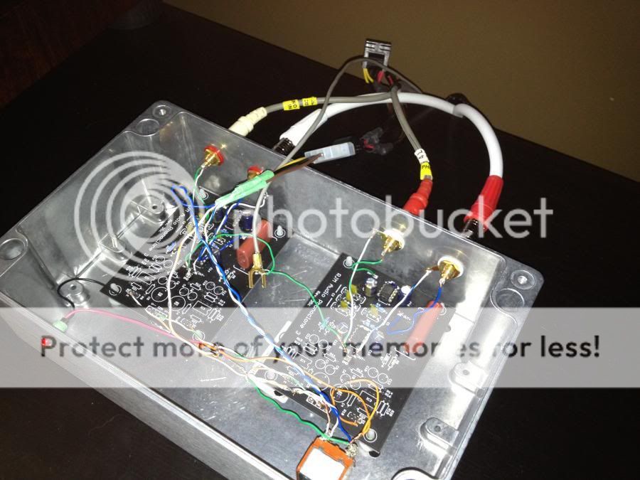
Hey all, wanted to post some pictures of my final build:
Sorry for the size...
An externally hosted image should be here but it was not working when we last tested it.
An externally hosted image should be here but it was not working when we last tested it.
An externally hosted image should be here but it was not working when we last tested it.
An externally hosted image should be here but it was not working when we last tested it.
Sorry for the size...
How big is big? 47 Labs uses one or two 170VA supply's but that's with 2 x 24V, 170 / 48 = 3.5A, 3.5 x 2x12 = 84 VA. Would 84 VA do? or is 2 x 50 VA (2 x mono) OK?
There's a quality vs. size (VA) issue, as well as a quantity (2 vs 1) issue. I can't answer that definitively, and I don't think its worth obsessing over.
Also don't forget that the 47 labs supply is a "one size fits all" model that will also power a gaincard amplifier. It is not purpose-built for a phono stage.
For the phonoclone/VSPS a single 25 VA toroid is sufficient. Anything above that is "try and see if the difference is worth it to you" territory.
I follow the 47 labs model and have several general purpose power supplies, all are 160 VA Plitrons, with both magnetic and electrostatic shields. Of course they work fine with the Phonoclone, but the point is they can be used for all sorts of different things. Buy one, build once, reuse. Cheaper in the long run.
Hey all, wanted to post some pictures of my final build:
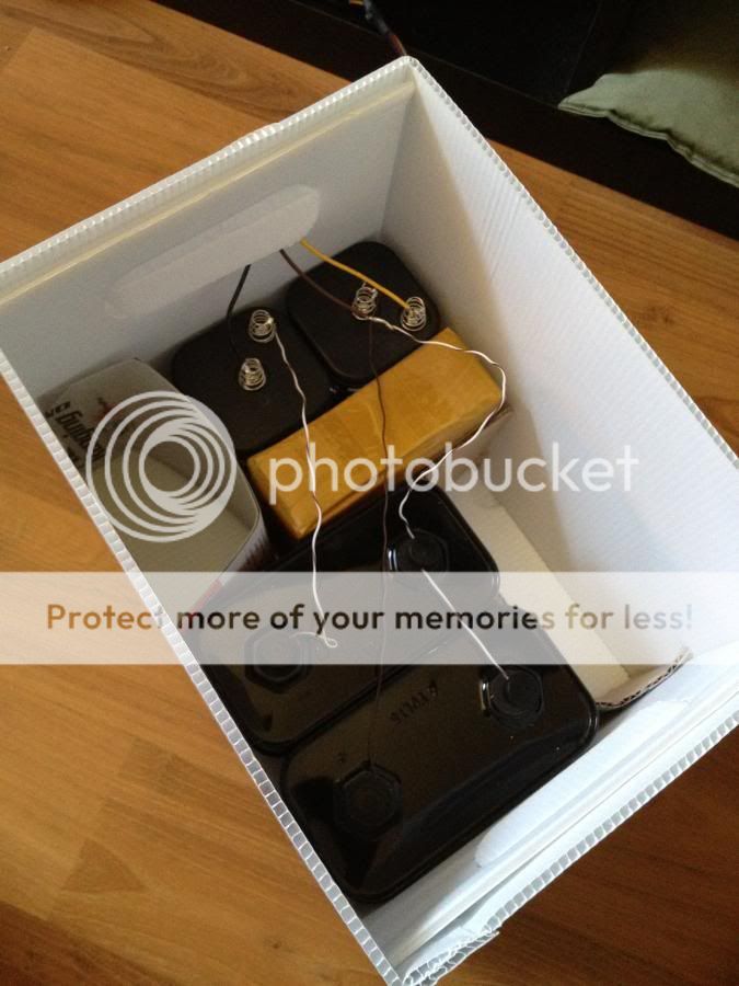
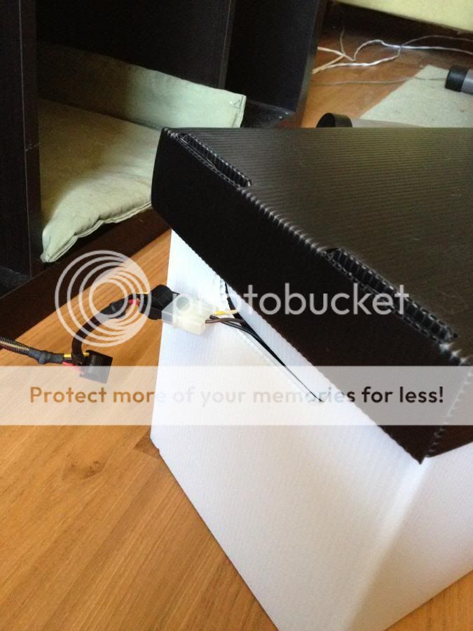
Photos of batteries in boxes with wires hanging out.
Hey Phil, you got it working in the end, congrats!
Are you using slow-blow "T"-typoe fuses? Normally 1A slow blow is sufficient.
Yep T Type.
Hammond warns about this in their page too. Anyway, 2A fuse works without problems.
Replaced the chinese caps with nichicons again.
It seems that two recaps is two desolderings too many... The thin pads for some of the electrolytics are marginally fubar.
May I suggest a bit bigger pads for your next revision? At least for the parts that people might play around with (mostly caps).
I hope you have spare kits waiting Richard. I will probably need a new set soon.
By the way, (you probably missed this before) I am getting a precision LCR meter next week. Do you think it would make a difference matching every component on the boards? Or should I just go for the RIAA parts ?
@Ronald
As I said on my previous post, the 120VA Hammond made a huge difference in comparison to the cheapish non-toroid 48VA. There is a huge difference in clarity, more evident on mid-highs and environmental sounds that give the sense of the room. The bass is also much more controlled, although a bit less impressive/warm (might need some more breaking in). I have a second one so I am definetely trying dual mono as well. I am also tempted to try an even bigger one and use the 120VA one to power my turntable ( QFT for Richard's remarks on general purpose power supplies)
The default components in Eagle have standard size, i.e. small pads. Great for high component density, commercial boards, not so great for dimkasta's experiments.
The pads will forgive one desolder-solder cycle. Two is pushing it.
This is OK for most people, and since changing it involves a huge amount of work (editing the Eagle component libraries is not at all fun) this is the way it will stay. Components that you want to switch in and out frequently should be mounted on pins. If you really want to do things like changing over full set of electrolytic capacitors, consider either building a prototype on vero or buying a small stockpile of boards...
Trying to precisely match components like the RIAA caps will only cause you grief. Trust me on this one, its better not to know.
OK fair enough about the pads
Can you please elaborate a bit more on the matching thing? I m reading a lot of people do it on RIAA parts. is that really that hopeless?
And something else.
Last few days, I m getting 220V on the network which result in 12V before the rectifiers, 11V after them.
I did not measure the opamp V since the boards were on the surgical table, but according to your excel, the V on pins 4 and 7 should be ~9,2V. Would this affect the performance?
Yep T Type.
@Ronald
As I said on my previous post, the 120VA Hammond made a huge difference in comparison to the cheapish non-toroid 48VA. There is a huge difference in clarity, more evident on mid-highs and environmental sounds that give the sense of the room. The bass is also much more controlled, although a bit less impressive/warm (might need some more breaking in). I have a second one so I am definetely trying dual mono as well. I am also tempted to try an even bigger one and use the 120VA one to power my turntable ( QFT for Richard's remarks on general purpose power supplies)
I wonder how much the different sound has to do with breaking in. A toroid will be better as a non-toroid I think but....
I myself am in the process of changing the electrolytics on the phono part of the Phonoclone and did notice the same effect but also that this effect decreases after a few days. I think you will need at least an 100 hours of breaking in before you can judge the new component or other change.
Ronald.
- Home
- Source & Line
- Analogue Source
- The Phonoclone and VSPS PCB Help Desk