@WntrMute2
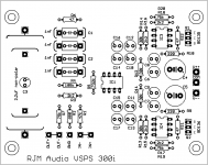
Sorry I don't have a photo, but the diagram is linked to from the pcb ordering page, scroll down to the image of the board, and the info is included if you click "download schematic".
For convenience I've also attached it, below.
@Carlp
Audacity I have used. I guess what I was thinking of is something really slick, where the audio sample was matched against an online database to ID the album and song info and make the cuts based on the reference info.
Failing that it's not worth the hassle. I'd just make archival recordings as one big file "side A", "side B" for each LP.
Attachments
Thanks Richard, helpful as always. I can't wait to get started. For those in the US, I found a source for what seems to be appropriate transformers. Shielded and all. I bought 2 for a dual mono supply at $17.50 each.
Antek - AS-0512
Antek - AS-0512
Richard , i'm just ordering the parts for the PCboards you sent . TY
try Spin It Again - Transfer vinyl LP to CD or convert tape cassette to CD and MP3! for transfer and splitting .")
cheers Woody
try Spin It Again - Transfer vinyl LP to CD or convert tape cassette to CD and MP3! for transfer and splitting .
cheers Woody
So I have some Solen caps as well as some Kimber Kaps and some generic caps for C3 of my VSPS. Any suggestions? Also, C3 is marked for polarity, the caps, all 3, don't have polarity marked. The Kimbers do have different colored leads, red and black, is this significant? Also, I need some reccomendation as to wire to hook up the XLR input from the power supply to the boards. As well as hook up wire from the inputs to boards and from boards to outputs. What gauge wire do you recommend for both of these applications? Should either or both inputs or outputs be shielded? I can twist some up but I found a source of what appears to be good quality silver plated copper stuff in 22-26 awg. either shielded or plain. Thanks.
Dave
Dave
All that stuff falls under the category of "personal taste". Generally you don't need to use shielded cable for the internal signal wiring, but twisting the +/- pairs together is good practice.
The black wire on the caps denotes the outer foil. It would normally go to the side with no DC bias applied. For C3 it doesn't but technically it would face the output rather than the op amp.
I use 16 or 18 awg or similar stranded copper for the internal power wiring, and 24 awg solid copper core for the signal wires. It depends on a) what you have lying around and b) whether you are more interested in how it sounds or how easy it is to manage the cable routing. Teflon wire might be desirable, but it a total pain to strip since it is so slippery.
Try Spin It Again - Transfer vinyl LP to CD or convert tape cassette to CD and MP3! for transfer and splitting .
Aha, yeah that's what I had in mind. Nothing fancy, but it automates the database search and data entry parts of the process, which makes all the difference, and it supports 24/192 format, which together is all I would need.
@Wirehead.be
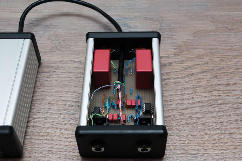
Great build. I'm still confused why you are using 1/4" jacks though.
An externally hosted image should be here but it was not working when we last tested it.
http://i3.photobucket.com/albums/y57/WntrMute2/Capacitors.jpgSo what about the caps without orientation marks such as the generics or the Solens? How are they to be positioned? Could you explain a little more about their positioning for my education? Thanks
Last edited:
Technically, it's a simple matter of the outer foil acting as a shield for the inner foil. So, the outer foil should be connected to the low impedance side, or ground, to reduce noise pickup. Also I suppose in high voltage application it is better for a safety aspect to have the outermost foil at low potential should it ever get exposed from the plastic wrap.
Though its true, I've never given it a moments thought before now. None of my foil caps have these markings, so I've never cared about which way to connect them. Multicaps, for example, may not even have this kind of internal construction anyway.
Though its true, I've never given it a moments thought before now. None of my foil caps have these markings, so I've never cared about which way to connect them. Multicaps, for example, may not even have this kind of internal construction anyway.
Rondo Bronze: DC impedance 6 ohm, 0.5 mV output. The impedance is low enough that it would be a nice match for a step up transformer, but it's also compatible with the Phonoclone if you want to go that route.
Thanks again, considering that my funds will be severely depleted after the cartridge purchase I will go the Phonoclone route as it is the most cost effective solution
Cheers
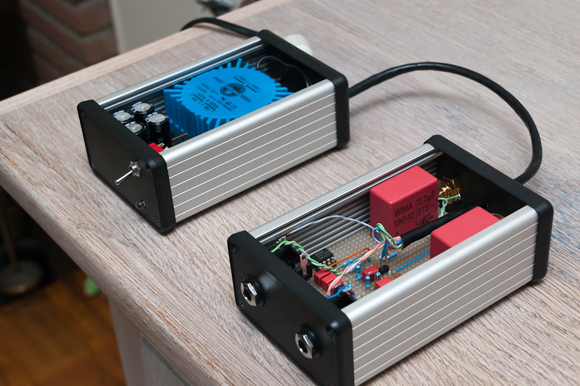
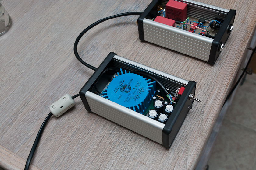
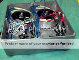
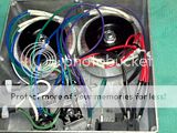
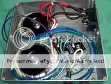
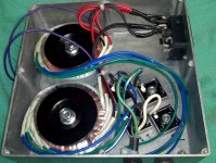
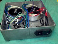
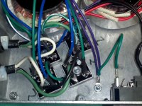
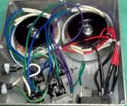
I've finished my power supply. My first project of this type. I've used 50VA Amtek transformers at $17 each. The IEC connector incorporates a fuse and lighted switch to simplify my hole drilling and wiring. I have the IEC on what I plan to be the side for access. The umbilicals (or is that umbilici) exit the back. Comments and suggestions welcome.
Dave
BYW, how do you get the pictures to enlarge. The little thumbnalis just move a bit when you click on them?
Dave
BYW, how do you get the pictures to enlarge. The little thumbnalis just move a bit when you click on them?


Last edited:
- Home
- Source & Line
- Analogue Source
- The Phonoclone and VSPS PCB Help Desk