Rather than reading the help thread, my homepage gives a more concise overview. Theres even a FAQ on the PCB ordering page. I realise it doesnt answer all your questions though, so I'll address them below-
Q. Will it sound better than X?
-Ouch. Just so you know, asking a question like that basically paints the word NEWBIE on your forehead in dayglo pink. A. If X is a commercial unit costing less than $800 then yes, probably.
Q. How much will it cost?
-If you cant, in your head, price up a BOM for the circuit just by looking at the schematic (give-or-take a quick browse through digikey or partsconnexion) then you probably arent ready for this. A. Obviously it depends on on how much you pay for the parts, and this varies enormously from individual to individual. Audiophile components, a nice case, and a high quality transformer might easily price out to $200 or more, but it can built just as easily for under $100.
Q. Are there off the shelf power supplies?
A. Split, unregulated, linear external power supplies are rare. You'll see, though, once you start this, that it isnt worth the effort even looking: just get a transformer and some diodes instead, both of which are easily sourced. That's all that's needed, and the result will cost less and sound better.
I have been asked the "will I be able to do this?" question several times in the past. I have generally set the bar at the following: if you cant run through the design and construction of an unregulated +/- 15 V split power supply then its unlikely you'll be able to build a working phonoclone without a awful lot of help. I generally discourage people who fall in this category from proceeding. Too much of a nuisance for me, and too much frustration for them.
That sounds harsh but it isn't really. A couple of weekends of self-study at the library, and maybe one more kit project under their belt and these same people can come back and do it all without incident, to great satisfation of all concerned.
Richard
Hi,
Thanks for your answer, and sorry for coming of like a newbie so much
I do understand the partslist provided on your webpage and have read the FAQ, I just wasn't sure ...
That split unregulated lineair PS looks Quite simple to learn and I'll probably be able to get some help on the PS part of the forum or on some other forum
Is that offer on the previous page really for the two phonoclone boards ( 20 dollar) ?
Robert
rjm said:
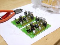
attached: Eagle brd and sch files for the phonoclone mini version 26i. I posted a similar board with RC filters and LM7x12s a while back. The most significant change is I updated my lbr files to have resistors and capacitors with wider pads and larger drill holes. In software jargon this version is RC2. Good to go, though I might have forgotton to dot an i somewhere.
/R
Looking at the board, wouldn't it be better if you can place the V-, V+, decoupling caps (C10,11,12,13) much closer to the IC legs?
Finally got around to building the RC filtered version of the Phonoclone mini. I should have a chance to case it up this weekend and see what it sounds like.
For the record the power rails are as follows
1000uF/25V Nichicon FW
LM7x10 10V fixed regulator
100uF/25V Nichicon FW
10R
100uF/25V Rubycon ZA
(output stage OP27)
10R
100uF/25V Rubycon ZA
(input stage OP27)
The FW are the replacement for the Nichicon Muse at the local store where I buy stuff (Digit in Nipponbashi if you must know). The ZA are ultra-low impedance types that I was given over a year ago but never got around to using as I was reluctant to stick them directly on the output of the regulator for fear of instability. Isolated by the 10R resistance as they are here it should be the ideal application.
/R
Attachments
Just completed a VSPS. Need some opinion on a problem I have. The two channels are not balanced in volume. One side is slightly louder than the other.
I have bought 1% resistors in lots of 10 and matched the best 2 for each value. One finding I have found, is that the +/- voltage after the onboard regulators are not spot on at 12V.
There is a small difference between the positive and negative and also between the left and right channel boards. This difference is in the range of about 0.5V.
Any comments are welcomed.
Thanks.
A slight spread in the regulator output voltages is normal and will not effect the strength of the VSPS output signal. 0.5 V is a little more than I would expect, but its still not a concern.
The gain is defined by the circuit components, R2 and R4 being the most important, but all the RIAA components count to some extent, including C1 and C2.
I can think of three possible causes:
The cartridge is damaged or poorly aligned. (unlikely, but check system with another phono stage)
You got mixed up when hooking up the components in one of the channels. (R4 and R3 switched around for example)
Some components overheated when you were soldering them in place, changing the value.
/R
Thanks RJM, will check the resistors.
I was worried re: the voltage and was thinking of moving the power regulators off the pcb and using an adjustable dual power supply to get more accurate supply voltages. Do you think this will cause any change to the sound quality?
Thanks.
I was worried re: the voltage and was thinking of moving the power regulators off the pcb and using an adjustable dual power supply to get more accurate supply voltages. Do you think this will cause any change to the sound quality?
Thanks.
What a coincidence.
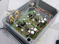
I've just finished putting the new version of the phonoclone together. I've had a chance to spend a couple of evenings listening to it now. Just like heady I noticed that a slight channel imbalance. Ive built enough of these now to identify the problem as mismatch in the RIAA eq filter rather than a difference in overall gain.
(Straight gain mismatch, say by mismatching R2, is just a direct pulling towards one speaker. An RIAA mismatch manifests as more a of a fuzzyness in the stereo image.)
In my case, I found after checking the resistors again that R6 was 741k and 771k. R5 was 112k and 113k. The mismatch in R6 translates as only a 1/4dB difference, mostly in the bass, but its an embarassing ****-up all the same: everything should have been within 0.5% or better.
I'll deal with this on the weekend, as well as hopefully have a chance to measure the frequency response and noise spectrum.
My early impression, comparing it to the BE version I presently use, is tentatively positive. I feel that the RCRC filtered power supply makes the phonoclone sound more organic. (I searched for the right word for some time, this seems the best description) I have lingering concerns however about whether it is also compressing dynamics. I also noted poor stereo imagine as explained above, and a lack of blackness around individual instruments.
I'll update later after Ive got the measurements done and given a chance for the capacitors to settle in properly.
/R
Attachments
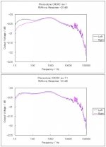
The problem was R5 and R6 were not matched. I thought they were but evidently not. R5 and R6 were 111.8k 769k left, 113.0k, 740k right. I replaced the right channel resistors with 110.5k and 763k. This change put the response back at a respectable balance between channels.
If I was sensible and used metal film resistors I could have done better still, but I still use carbon films, 5% tolerence, and they can often change 1% of their value when soldered. I dont always get exactly what I want in the package of 10, iether.
On the other hand, we are talking about less than 0.2 dB response error, and less than 0.05 dB channel mismatch. I call that pretty good.
In the data please ignore the response above 10k. Not accurate and not pretenting to be.
The gain as measured is 60 dB, with an input load was 36 ohms and output load of 15k.
Regarding noise, to be honest the FFT looks like the unfiltered versions: a little peak at 60 Hz, and a sprinkling of harmonics 10 dB or less above the noise floor up to frequencies of 1kHz. I dont think this is from the power supply directly, but rather stray pickup through the inputs somewhere. The testing environment isnt ideal and I dont think theres much point in persuing it further.
/R
Attachments
cartridge loading
Thanks again RJM for all your hard work, I am sure I can speak on everyones behalf and again say thanks.
I am still using the originals you built for me but now with the capacitor position change sugested way back. Original basic power supply....Still very happy
First, I searched the posts but did not see an answer [I may be blind]....
Based upon the fact that I am happy with the output gain amplitude...and I have a denon DL103...Output Impedance 40 ohms....Load Impedance > 100 ohms.... output .3mv
R1 47R (Denon DL103, set equal to cartridge impedance)
R2 6k8 (Denon DL103, 75dB gain, calculate for desired cartridge/gain)
If I want to retain the the same setting on my volume control at my pre-amp.
My new Cartridge is ....Output Impedance 16 ohms......Load Impedance 150-1000 ohms....output .29mv
The prefered load for this cart, based upon listening reviews is in the 1-1.5K ohm mark
Based upon the above, please what changes should I make.
Secondly, for all those that are like me and probably happy with their originals but itch to improve [based upon your valuable time] can you please provide details of how to upgrade including power supply and component type changes [regulators] please again based upon your knowledge and expertise.
Simple english for those amongst us [me] that are a little slow electronically.
Again, thank you for all your time, help and assistance in the past and also for the ongoing future.
Thanks R,
If the advised preferred loading for the new cart is now revised to between 47k ohm and 100k ohm based on further listening reviews what changes need to be made.
Sorry for my ignorance, My question relates I suppose to what changes to make if any for this circuit if one is changing the preferred loading to alter the sound of the cart . Therefore for preferred cart loading to be ....
1k load change R1? = no change
47K load change R1 ? = ?
100k load change R1 ? = ?
again many thanks
Ah, I see where the confusion is:
R1 is not the cartridge load, and has nothing to do with the manufacturers recommendation. R1 is chosen to be roughly equal to the internal impedance of the cartridge so that the opamp "sees" equal impedances on the inverting and noninverting inputs.
1k load change R1? = cartridge output impedance
47K load change R1 ? = cartridge output impedance
100k load change R1 ? = cartridge output impedance
In your case its 16 ohms, so R1 should be 16 ohms, but its not important that it exactly match.
The phonoclone has zero input impedance - all cartridges see a virtual short circuit as the load. There is no circuit adjustment to be made for the manufacturers recommended loading. By using a phonoclone you are choosing to ignore their advice anyway.
/R
Thanks R,
Thanks, now I understand better.
If I was being a perfectionist/pedantic would I thus make R1 =16 ohms and R2 =2.7k ohms
Please, I am mistified by your comment...
By using a phonoclone you are choosing to ignore their advice anyway.
Is this a reflection upon the circuit as per 47 Labs and yours and the philosphy of the design in its method of achieving a result or is this comment based upon just your design.
I feel your comment refers to the 1st but please explain.
I value your opinion also of this design against what would be considered a normal design and its method of execution and the final result one could expect.
- Home
- Source & Line
- Analogue Source
- The Phonoclone and VSPS PCB Help Desk