Hi guys, question re PSU for phonoclone-
i 've built one using 100VA 2+12VAC toroid-
the measured Voltage after rectifier is 11.5. Is there a problem? I thought it is a bit low.-was kind of expecting 18 or so.
recheck again-fuse blown-must be short somewhere.
1. You won't measure 18 V DC until the phono stage board is connected to the power supply. Disconnected, the voltage at the power supply after the rectifiers is about 12 V DC.
2. You must use a use a slo-blo or T type fuse. 0.25 A should be fine.
3. You can't measure 11.5 V on the output and have the fuse open. That makes no sense.
it's useful way of my project.
it could be the problem with the fuse-i asked for time delay fuse but instead they gave me Q type fuse?
The problem is that everytime i turn it on then the fuse is blown.
Q=quick, and that's your problem. The inrush current trips the fuse every time you turn it on. The fuse is doing its job, it's just that its the wrong kind of fuse for this application. You need type T or S for slow, whatever they call it 'round your way.
@AndrewT : next to the rectifier is the worst place for the filter caps. For a number of reasons, but the most relevant here is that these are also the bypass caps for the op amp, and should therefore be placed as close to the op amp as possible. I've tried numerous configurations of parallel caps at various positions, and they all sounded worse than the present arrangement.
If one minimises the lengths between the transformer and the client circuit, then I am inclined to agree.next to the rectifier is the worst place for the filter caps. For a number of reasons, but the most relevant here is that these are also the bypass caps for the op amp, and should therefore be placed as close to the op amp as possible. I've tried numerous configurations of parallel caps at various positions, and they all sounded worse than the present arrangement.
But, when the transformer is remote from the client circuit then compromises must come into play.
I believe it is better to keep the charging pulses very local to the transformer AND to have sufficient decoupling of the correct type located very close to the client.
This demands rough smoothing at the rectifiers, send DC down the power lines and fit decoupling next to the opamp. One can add some inductance and/or resistance to the remote power lines to create CRC or CLC type supplies.
The overall effect is that the pulsing of the PSU is kept away from the opamp/poweramp and let's the HF PSRR get a better chance of keeping the audio clean.
I guess I don't share your view that it is particularly important to keep these charging pulses of current localized to the power supply. As long as the board layout is sensibly designed to keep these currents off the signal grounds, of course. In principle there could be induced interference from the wires etc, and no, it's not a setup I would use in non-audio (i.e. scientific) instrumentation, but I haven't observed to be an issue in practice with the phono stages I've designed.
I'm not saying CLC CRC etc. won't work, and I've had success enough with them in high voltage applications i.e. tube amps, but with op amps I've never been really happy with the resulting sound, in the same way as the "textbook" parallel bypass arrangement of say 100 uF and 0.1 uF has never worked for me either.
I'm not saying CLC CRC etc. won't work, and I've had success enough with them in high voltage applications i.e. tube amps, but with op amps I've never been really happy with the resulting sound, in the same way as the "textbook" parallel bypass arrangement of say 100 uF and 0.1 uF has never worked for me either.
guys,
got my phonoclone 3 put together into my system. Sounds good so far.
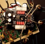
It's got almost no notable hum, however with it cranked up on idle, I get a bit of hash-noise. I think it's the diode blocks. I tried putting 100pf at C0. get the same amount of noise. Would using something akin to a MUR860 and some 10pf caps across them help reduce this noise? Is the diodes what I am hearing.
My speakers are very sensitive, so makes this noise a bit more notable.
got my phonoclone 3 put together into my system. Sounds good so far.
It's got almost no notable hum, however with it cranked up on idle, I get a bit of hash-noise. I think it's the diode blocks. I tried putting 100pf at C0. get the same amount of noise. Would using something akin to a MUR860 and some 10pf caps across them help reduce this noise? Is the diodes what I am hearing.
My speakers are very sensitive, so makes this noise a bit more notable.
I am using a DL-103, r1 47 ohm, and 1.5k r2. I thought that was recommended.
What should I shoot for? A little gain loss would not be a bad thing.
With sensitive speakers with the volume cranked up, the hiss/hash will be quite loud. What you are most likely hearing, though, is the fundamental op amp output noise. The diode spikes don't normally show above that, with the phonoclone 3 design anyway.
r2 1.5k is the recommended value, or at least 1.3k is, as per the latest BOM worksheet, but reducing the gain will certainly reduce the output noise. The signal to noise ratio remains ~constant, this is no "fix" as the noise source is fundamental to the op amp. If it makes for a more comfortable match to your system, though, by all means drop r2 to 680 ohms or so, which knocks the gain by 5-6dB from 60 dB to a still respectable ~54 dB.
Last edited:
Hi RJM...I've just Built your 6DJ8 Phono Amp and it Sounds Great!....I was wondering if you have a Thread about this too.
http://www.audiokarma.org/forums/showthread.php?t=233322
http://www.audiokarma.org/forums/showthread.php?t=233322
No, no we don't have a thread about the 6DJ8 Phono Stage, though several people have built it and, like you, been happy with the result. I suppose that's because no one has needed "help" with it...
From time to time I toy with the idea of updating/improving it, but each time decide there isn't much to be done really. The solid state version of the power supply version could use a refresh though.
From time to time I toy with the idea of updating/improving it, but each time decide there isn't much to be done really. The solid state version of the power supply version could use a refresh though.
")
Question about the dual rectifier setup. I have a working single bridge rectifier setup but can't get my head wrapped around the new improved dual setup.
I have tried a few different ways to wire the secondaries based on the examples mentioned in this forum and I either blow a fuse or get close to 30V dc on the outputs!
I am using the following transformer:
http://www.antekinc.com/pdf/AN-1212.pdf
GBPC Bridge rectifiers:
http://www.fairchildsemi.com/ds/GB/GBPC1202.pdf
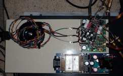
Any ideas on what I may be doing wrong? I can post pictures later today if folks want to take a closer look at the wiring.
Thanks.
I have tried a few different ways to wire the secondaries based on the examples mentioned in this forum and I either blow a fuse or get close to 30V dc on the outputs!
I am using the following transformer:
http://www.antekinc.com/pdf/AN-1212.pdf
GBPC Bridge rectifiers:
http://www.fairchildsemi.com/ds/GB/GBPC1202.pdf
Any ideas on what I may be doing wrong? I can post pictures later today if folks want to take a closer look at the wiring.
Thanks.
Dual Rectifier Setup
Question about the dual rectifier setup. I have a working single bridge rectifier setup but can't get my head wrapped around the new improved dual setup.
I have tried a few different ways to wire the secondaries based on the examples mentioned in this forum and I either blow a fuse or get close to 30V dc on the outputs! This measures 24dc at the opamp on the v-, v+ pins.
I am using the following transformer:
http://www.antekinc.com/pdf/AN-1212.pdf
GBPC Bridge rectifiers:
http://www.fairchildsemi.com/ds/GB/GBPC1202.pdf
Any ideas on what I may be doing wrong? I can post pictures later today if folks want to take a closer look at the wiring.
Thanks.
- Home
- Source & Line
- Analogue Source
- The Phonoclone and VSPS PCB Help Desk