New Board 3*7 Regulation
I found it convenient to use variable regulation for the 3*7. You can adjust the voltage precisely and you can use different voltage supply +-10V, +-12V, +-15V just for exploration. I think variable resistors do no cost that much and results are more flexible.
- BSPX
I found it convenient to use variable regulation for the 3*7. You can adjust the voltage precisely and you can use different voltage supply +-10V, +-12V, +-15V just for exploration. I think variable resistors do no cost that much and results are more flexible.
- BSPX
Member
Joined 2004
This is wa-ay off topic, but ...
Japan Post is also the country's largest saving bank, with some trillion dollars in the vault. The polical moves are all about who gets to control this piggy bank, and how the money gets reinvested into the country's economy. Nothing to do with the mail service, which is stellar, or even its inefficiency.
/R
Conversion to VSPS Ulra
Richard it appears to me that the conversion of the VSPS boards to take a VSPS Ultra requires:-
1) the removal of R1 and R2
2) the cutting of IN+ to IC+ track near the IC.
3) Bridge between part of track comming from IN+ to track going
from C1 to IC-
and 4) Bridge from IC+ solder pad to COM track.
Is this correct or is there an easier way?
BT
VSPS to VSPS Ultra PCB mod
Hi,
Sorry about the not getting back to you by email - but it was a bit more involved a question than I had time for this week.
Ok, double check everything I write here: I havent done the mod myself.
In its simplest form, the mod is as follows: use R1=10ohms, or bridge the pads with wire, leave out R2, and connect the input wire to the top pad where R2 would normally go.
/R
")
Question about lm317/lm337 regulation
I have a question about lm317/lm337 regulation.
Lets say for an output of 15v we set R1 = 121ohms and R2 = 1330ohms. If the maximum possible current (Iadj) flowing through R2 is 100uA (from datasheet) then the voltage across R2 (also across C2) is 0.0001 x 1330 = 0.133volts. Is this correct?
I am asking because I want to use a 22uF/6.3v Blackgate Nx for C2 and I want to make sure the voltage rating will suffice.
I have a question about lm317/lm337 regulation.
An externally hosted image should be here but it was not working when we last tested it.
Lets say for an output of 15v we set R1 = 121ohms and R2 = 1330ohms. If the maximum possible current (Iadj) flowing through R2 is 100uA (from datasheet) then the voltage across R2 (also across C2) is 0.0001 x 1330 = 0.133volts. Is this correct?
I am asking because I want to use a 22uF/6.3v Blackgate Nx for C2 and I want to make sure the voltage rating will suffice.
ran_ph
100uA is the maximum current flowing out of the adj terminal, and you can ignore it for this discussion unless you make R2 extremely large. The max voltage normally seen by C2 is Vout*(R2/(R2+R1) i.e. pretty much all of Vout. The voltage rating on C2 should be equal or greater than Vout. Personally I prefer to be safe and rate all the caps for 25V. You can't use a 6.3V part there, at any rate.
BT
one point I forgot re the VSPS ultra, the input ground can be attached either to the bottom pad of R2 (safest bet) of the original IN- pad. Shouldn't matter which.
-rjm
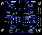
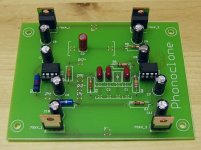
For the guys who recently got a Phonoclone PCB and a bag of parts in the mail, this is approximately what it should look like when the board is finished.
C1: the 102G cap is 1nF
C2: the 222G is 2.2nF and the 681 is 0.68nF, in parallel they total 2.88 nF.
you can also use 4x 1nF caps for 1nF and 3 nF respectively.
I've sort of settled on Matsushita carbon film resistors for the R5, R6, Riken Ohm for R1 and R2, and Takano carbon composition for R3, R4 and R7, R8. I will probably make a full parts kit available for the next batch order, including the resistors for the first time.
I'm also considering offering 25A bridge rectifiers and silver mica RIAA caps. Though neither of these are cheap, they are the parts I'd use myself, so it only seems fair to add these to the order list.
-Richard
Attachments
Phonoclone Up and Running
Hi There,
As one of the recipients RJM refers to in the post above I thought I'd just mention that my PhonoClone boards and parts arrived last Sunday and that my PhonoClone is now singing sweetly!
It's spread out on the bench as present - I haven't even begun to build a case but the initial results are very encouraging, I think I have a little too much gain with R2 at 1K5 (I'm using an Ortofon Kontrapunkt b 470uV 5OHM internal DC resistance and recommended load 50-200 Ohms) -- any suggestions for an R2 value to give me a little less gain and suite this cartridge ?
Thanks
Dave.
Um, are we talking about the same thing?
The RIAA caps in the Phonoclone are in the order of 1 nanoFarad, and silver mica caps are typically about 10x8x4mm in size, depending on the actual voltage rating and capacitance of course. Only a little larger than film/foil types, in fact.
I believe most brands have tinned copper lead wire, so I dont expect them to be any more magnetic than, say, any other cap you might use.
And old but interesting article on capacitor "sound" : Capacitor Types (of course other factors like inductance may be important, this page just looks at voltage hysteresis)
Polystyrene and polycarbonate appear to be in the same class as silver mica, for what its worth I think any of those would be fine in this application.
/R
Attachments
![micacaps[1].jpg](/community/data/attachments/32/32425-2dc60515a5d5677bfcce0c78cdfafb8e.jpg)
Maybe over there
rjm said:Most are real small. The 3000 pf ones I found are pretty large. Those have copper leads.
CDE is the brand most readily available here. Almost all of them have steel leads. So do some of the SAHA, Sang,San, ADM, and others. Sometimes the makings are identical, a few are copper, the majority steel.
It used to be better, maybe 50% were steel, now 90% are. I keep a magnet in the car for capacitor and resistor shopping.
In Japan they may still have a lot of copper leaded ones. The Soshin brand are real nice, but hard to find here. All I have seen have copper leads.
The 0.1 ufd 500v silver mica cap I mentioned is almost three inches long, inch deep, and a half inch thick. Welding rod is a little big, maybe wire coat hanger size leads. A monster size cap. All to get 0.1 ufd.
I guess rather than try the big 3000 pf, I will take your advice and parallel values to make a 2900 pf. This will be lower inductance. And the leads should fit through the circuit board without reaming the holes.
This is an issue with using old parts to build things. The leads were larger on some of the passives 30 - 40 years ago. They will not fit the holes if drilled for modern parts.
George
Um, are we talking about the same thing?
The RIAA caps in the Phonoclone are in the order of 1 nanoFarad, and silver mica caps are typically about 10x8x4mm in size, depending on the actual voltage rating and capacitance of course. Only a little larger than film/foil types, in fact.
I believe most brands have tinned copper lead wire, so I dont expect them to be any more magnetic than, say, any other cap you might use.
And old but interesting article on capacitor "sound" : Capacitor Types (of course other factors like inductance may be important, this page just looks at voltage hysteresis)
Polystyrene and polycarbonate appear to be in the same class as silver mica, for what its worth I think any of those would be fine in this application.
/R
- Home
- Source & Line
- Analogue Source
- The Phonoclone and VSPS PCB Help Desk