looking for a chassis, well, maybe not chassis, but an enclosure for the VSPS to shield it from the rest of the pre-amp. I want to build a pre-amp that can use a less expensive transformer, and also contain a rotary switch for input (and maybe output) selection. I am thinking I can get an inexpensive aluminum (sheet metal, or extruded) inexpensively, and plave the VSPS inside. I can then mount this inside a larget enclosure that will hold the power supply, and the input output terminals and switch(es).
One important thisng to know: What is the expected height of the VSPS board with components on it? I know it depends on the capacitors used, but a min and max would help.
Any examples of builds like that, a phono stage PC board, inside a shielded box, inside say a rack mount size chassis that contains 'other stuff'?
To fill in some info related to the last few posts:
Re. Carbon resistors. The 47 ohm carbon composition resistors are chosen for having low inductance, and used as a damping resistor on the output of the op amps. In this application the higher noise values are inconsequential.
Neither the value nor the type of resistor is important. Anything between 30 and 100 ohms is fine, and it can be any type/brand you like. It's purpose is to isolate the op amps feedback circuit from the capacitance of the interconnect cables.
Re. Op amps. You'd have to specify which op amp you want to substitute. There may be cheaper alternatives, either generic brand or equivalent model, or it may be that the op amp you found is not ideal for the circuit. Op amps designed for audio tend to be more expensive than general-purpose types.
Re enclosures. It's always better to give yourself more space than you think you need. The VSPS board requires about 5 cm of chassis height, including the standoffs.
H rjm,
Correct, with no DC you shouldn't have any noise. However, given how much inductance a decent metal film resistor has, I would just use those. Carbon composition resistors are getting far more expensive and difficult to source.
With regard to enclosures ... heck YES! Within reason, more space allows you to space things out and avoid noise pickup.
Thanks for the explanation.
I found this op amp on Mouser that seems to fit the bill, LME49720NA/NOPB
This would be for a VSPS build. The NE5532 is about half the price of the LMExxx. Both are for hifi audio. The NE5532A is very inexpensive, it it REALLY the choice over something else like the one I mentioned?
Just concerned that I would be selecting something that has been surpassed.
Roger
While its fair to say that the LME49720 is a "new, improved" NE5532, you may or may not find it sounds better. I like the slightly gritty, organic sound of the NE5532. The main alternative is the OPA134, as it's FET input may play better with certain cartridges vs the bipolar inputs of the NE5532/LME49720.
My advice is to use a socket and try a few different ICs to see which one works best for you.
My advice is to use a socket and try a few different ICs to see which one works best for you.
Just make sure to order the dual OPA2134 for the VSPS.The main alternative is the OPA134
For phono preamps I also like the NJM2068DD.
@WizardWG4 Right, OPA2134. My brain defaults to singles when discussing op amps.
@rogerayotte To order, you send me an email, which you did on Oct 5th. Did you not get my reply? I use Paypal for the transactions, so if you don't have an account you'll need to ask someone who does to pay me for the order on your behalf.
@rogerayotte To order, you send me an email, which you did on Oct 5th. Did you not get my reply? I use Paypal for the transactions, so if you don't have an account you'll need to ask someone who does to pay me for the order on your behalf.
I've finished building my VSPS phono stage and installed it in a suitable enclosure. It's attached by umbilical to a separate-chassis power supply built to the specifications of the Construction Guide (that has been functioning well with a Phonoclone unit I built more than a decade ago. Now I can switch the power umbilical between the enclosure containing the Phonoclone, and another, new enclosure containing the VSPS. The former works with a Denon 103 on one turntable; the latter is intended to work with a Shure V-15 Type III on another.)
Is there any set of procedures I should follow before trying the VSPS with my turntable and pre-amp? In particular, what kind of realistic DC offset, if any, should I be looking for on the output of the VSPS? Anything else I should watch for?
Thank you.
Is there any set of procedures I should follow before trying the VSPS with my turntable and pre-amp? In particular, what kind of realistic DC offset, if any, should I be looking for on the output of the VSPS? Anything else I should watch for?
Thank you.
Well, I feel like big dummy now. Examination of the schematic shows capacitor C3 in series with the positive output lead, so of course there is no DC offset between that lead and circuit ground. Duh! (First, I measured with my trusty old Beckman multimeter, and said: "Wow, zero offset either channel! That's pretty impressive!" Then, I consulted the schematic and said: "Oh...").
@Zapped 
With the multimeter, I'd do a quick "walkaround" of the op amp IC pins, confirming the power pin voltages are correct and the output offset is reasonable. But really, it's all pretty foolproof. The only important pre-check before trying it in your system is the "smoke test". If it's powering up it's probably good to go.
With the multimeter, I'd do a quick "walkaround" of the op amp IC pins, confirming the power pin voltages are correct and the output offset is reasonable. But really, it's all pretty foolproof. The only important pre-check before trying it in your system is the "smoke test". If it's powering up it's probably good to go.
Thank you Mr. Murdey! I will do as you suggest, just for information purposes. I actually went ahead yesterday and connected the VSPS to my workbench system ( a tiny class D integrated amp I got from Parts Express for testing and background music in the garage; and some old Realistic Minimus 7 speakers) using my Shure V-15 Type III / Grace 707 as the source. And it works great!! Now that I know that, I can't wait to take that turntable and the VSPS inside and listen to it on my current main system (Wayne Colburn's diyAudio Line Stage, diyAudio Pass F6, and Magneplaner MG-IIA speakers).
Thank you for making this fine piece of audio design available to the DIY community! When I bought the Shure V15 and Grace 707 back in the mid-1970's I was using them with some pretty unremarkable electronics. Now I'll get the best out of these fine old source components!
Thank you for making this fine piece of audio design available to the DIY community! When I bought the Shure V15 and Grace 707 back in the mid-1970's I was using them with some pretty unremarkable electronics. Now I'll get the best out of these fine old source components!
any suggestions for PS chassis/enclosure? Want something 'cost effective' (meaning I do not want to use the word cheap).
Also, what is the minimum power for the transformer for a VSPS? The web site says 25VA or so, that seems high, but I am not the engineer.
I have a traditional transformer 36vac CT, but it is 100VA, and kind of largish.
Trying to keep costs down a little, I know it is hard to do in this Audio hobby all the time, but believe me, times require it right now.
Roger
The transformer should be 24 vct or 2x12 VAC. 25VA is a good balance of price, size and performance. Smaller ones don't tend to be much cheaper.
Not an endorsement, but this should do the job nicely, if you don't want to get the Triad toroidals from Mouser etc.
https://www.ebay.com/itm/195372633898
Yes I know it's 30VA but the smaller ones only have a single secondary winding.
As for cases, you're on your own! I prefer Hammond or Takachi cast aluminum project boxes, but plenty of alternatives on ebay etc. Just avoid the biscuit tin builds, please.
A little confused here. First of all my CT transformer only has a common center tap, not two. I am assuming that it is just the two tied together.
In the guide, the schematic for power supply shows the positive and negative poles of the rectifiers connected. In the spreadsheet, the schematic shows the two separate (positive and negative) poles of the rectifier go to the common on the phono board.
Since I only have a single center tap, I am confused as to how to connect this up. I have wired the rectifiers up to my transformer in the way I think is correct. The trouble is that the two poles of the rectifier that you show connected in the guide have a DC potential across them. It appears that they have the same potential as the two outputs, +18vdc, and -18vdc.
I think when I tried this initialls, there was some issue, and the transformer made a loud hum, and got very warm, hot even, so I shut it down and checked and rewired. Now there is no smoke, but I have not connected the two 'commons'.
Please help, I will try to post a drawing or schematic of what I have done.
Roger
Attachments
@rogerayotte
Hi Roger,
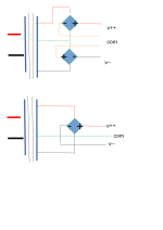
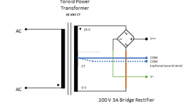
If you have a center-tapped 24 VAC secondary, as opposed to dual 12 VAC, you must use a single bridge rectifier.
This is the standard, textbook connection (see attached image). The COM now connects back to the center tap. A second COM wire can be optionally used if it's more convenient (to have two twisted pairs rather than a 3 wire braid for example). My boards have two COM pads to make this redundant connection intuitive.
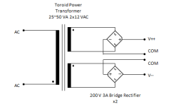
The double-bridge configuration is a more foolproof connection for beginners to deal with as the phase of the secondary windings isn't important. Just hook up each secondary to a bridge. Of course, you can connect the windings in series and use just one diode, but that involves correctly identifying which end of each winding is which phase ... and that's something that people are inevitably going to screw up. That's why I've generally avoided recommending this route.
I also found, in testing a long time ago, that the dual bridge configuration sounded better but I wouldn't swear to it and I'd probably use a single bridge if I was building one today.
Hi Roger,
If you have a center-tapped 24 VAC secondary, as opposed to dual 12 VAC, you must use a single bridge rectifier.
This is the standard, textbook connection (see attached image). The COM now connects back to the center tap. A second COM wire can be optionally used if it's more convenient (to have two twisted pairs rather than a 3 wire braid for example). My boards have two COM pads to make this redundant connection intuitive.
The double-bridge configuration is a more foolproof connection for beginners to deal with as the phase of the secondary windings isn't important. Just hook up each secondary to a bridge. Of course, you can connect the windings in series and use just one diode, but that involves correctly identifying which end of each winding is which phase ... and that's something that people are inevitably going to screw up. That's why I've generally avoided recommending this route.
I also found, in testing a long time ago, that the dual bridge configuration sounded better but I wouldn't swear to it and I'd probably use a single bridge if I was building one today.
Attachments
Last edited:
Thanks Richard. I worked out the single bridge circuit last night but I have decided that the transformer I was going to use is too high voltage (+-18vac). I think the voltage regulators would not have an issue, but I have 12vdc relays, and another board that takes 12vdc that I want to power from this power supply, so I am ordering a single primary/dual secondary (12vac, 12vac) transformer. I will use the dual bridge diagram as this transformer has two separate output windings and four output leads.
Thanks again.
Roger
Thanks again.
Roger
- Home
- Source & Line
- Analogue Source
- The Phonoclone and VSPS PCB Help Desk